Lexus ES: Removal
REMOVAL
CAUTION / NOTICE / HINT
The necessary procedures (adjustment, calibration, initialization or registration) that must be performed after parts are removed and installed, or replaced during rear height control sensor sub-assembly LH removal/installation are shown below.
Necessary Procedure After Parts Removed/Installed/Replaced (for HV Model)| Replaced Part or Performed Procedure | Necessary Procedure | Effect/Inoperative Function When Necessary Procedures are not Performed | Link |
|---|---|---|---|
| *1: for LED Type Turn Signal Light | |||
| Rear height control sensor sub-assembly LH | Perform headlight ECU sub-assembly LH initialization*1 | Lighting system (for HV Model) | |
| Replaced Part or Performed Procedure | Necessary Procedure | Effect/Inoperative Function when Necessary Procedure not Performed | Link |
|---|---|---|---|
| *1: for LED Type Turn Signal Light | |||
| Rear height control sensor sub-assembly LH | Perform headlight ECU sub-assembly LH initialization*1 | Lighting System (for Gasoline Model) | |
PROCEDURE
1. REMOVE REAR WHEEL (for LH Side)
Click here .gif)
2. REMOVE REAR HEIGHT CONTROL SENSOR SUB-ASSEMBLY LH
NOTICE:
If the rear height control sensor sub-assembly LH has been struck or dropped, replace it with a new one.
(a) for 2WD:
(1) Disconnect the connector.
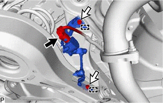
.png) | Connector |
.png) | Bolt |
(2) Remove the 2 bolts.
(3) Disengage the 2 guides to remove the rear height control sensor sub-assembly LH.
(b) for AWD:
(1) Disconnect the connector.
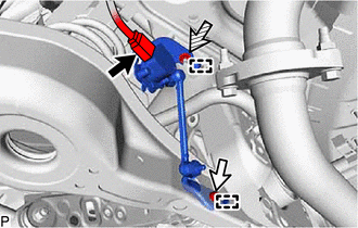
| | Connector |
| | Bolt |
 | Nut |
(2) Remove the bolt and nut.
(3) Disengage the 2 guides to remove the rear height control sensor sub-assembly LH.
READ NEXT:
 Inspection
INSPECTION PROCEDURE 1. INSPECT REAR HEIGHT CONTROL SENSOR SUB-ASSEMBLY LH (for 2WD) (a) Preparation for check (1) Confirm the standard, high and low positions of the link that will be used in the fol
Installation
INSTALLATION PROCEDURE 1. INSTALL REAR HEIGHT CONTROL SENSOR SUB-ASSEMBLY LH NOTICE: If the rear height control sensor sub-assembly LH has been struck or dropped, replace it with a new one. (a) for 2W
High Mounted Stop Light Assembly
ComponentsCOMPONENTS ILLUSTRATION *1 CENTER STOP LIGHT SET - - RemovalREMOVAL PROCEDURE 1. REMOVE CENTER STOP LIGHT SET (a) Disengage the 4 guides as shown in the illustration. D
SEE MORE:
Lost Communication with Airbag System Control Module Signal Plausibility Failure (P310764)
DESCRIPTION Refer to the description for DTC P310711. Click here DTC No. Detection Item DTC Detection Condition Trouble Area MIL Warning Indicate P310764 Lost Communication with Airbag System Control Module Signal Plausibility Failure Abnormal communication signal: Communicati
Cooling Fan Circuit
DESCRIPTION The ECM calculates an appropriate cooling fan speed based on the engine coolant temperature, air conditioning switch status, refrigerant pressure, engine speed and vehicle speed, and sends a signal to the cooling fan ECU (fan with motor assembly). The cooling fan ECU (fan with motor asse
