Lexus ES: Removal
REMOVAL
PROCEDURE
1. REMOVE REAR NO. 1 FLOOR BOARD (for 2GR-FKS)
| (a) Remove the 4 clips (A). |
|
.png)
(b) Disengage the 3 grommets (B) and 2 clips (C) to remove the rear No. 1 floor board.
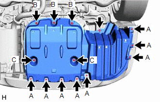
2. REMOVE REAR FLOOR SIDE MEMBER COVER (for A25A-FXS)
| (a) Remove the bolt and 8 clips (A). |
|
.png)
(b) Disengage the 3 grommets (B) and 2 clips (C) to remove the rear floor side member cover.
3. REMOVE REAR FLOOR SIDE MEMBER COVER (for A25A-FKS)
| (a) Remove the bolt and 8 clips (A). |
|
(b) Disengage the 3 grommets (B) and 2 clips (C) to remove the rear floor side member cover.
4. REMOVE SUSPENSION TOWER DAMPER
| (a) Remove the 2 nuts and the suspension tower damper from the vehicle. NOTICE: Do not extend or compress the damper. |
|
.png)
READ NEXT:
 Inspection
INSPECTION PROCEDURE 1. INSPECT SUSPENSION TOWER DAMPER (a) Visually check the suspension tower damper and, if the rod is bent, a leak is found or the damper cannot be installed without extending or c
Installation
INSTALLATION PROCEDURE 1. INSTALL SUSPENSION TOWER DAMPER (a) Using a union nut wrench, install the suspension tower damper to the vehicle with the 2 nuts. Torque: Specified tightening torque : 3
Installation
INSTALLATION PROCEDURE 1. INSTALL SUSPENSION TOWER DAMPER (a) Using a union nut wrench, install the suspension tower damper to the vehicle with the 2 nuts. Torque: Specified tightening torque : 3
SEE MORE:
Taillight Relay Circuit
DESCRIPTION The main body ECU (multiplex network body ECU) controls the operation of the TAIL relay. WIRING DIAGRAM CAUTION / NOTICE / HINT NOTICE:
Inspect the fuses for circuits related to this system before performing the following procedure.
Before replacing the main body ECU (multiplex net
Pressure Control Solenoid "D" Circuit Short to Ground or Open (P271314)
DESCRIPTION Refer to DTC P27137F. Click here DTC No. Detection Item DTC Detection Condition Trouble Area MIL Memory Note P271314 Pressure Control Solenoid "D" Circuit Short to Ground or Open While the engine is running, a short to ground or open is detected in the solenoid (
© 2016-2026 Copyright www.lexguide.net
