Lexus ES: Removal
REMOVAL
CAUTION / NOTICE / HINT
The necessary procedures (adjustment, calibration, initialization or registration) that must be performed after parts are removed and installed, or replaced during steering column assembly removal/installation are shown below.
Necessary Procedures After Parts Removed/Installed/Replaced (for Gasoline Model)| Replaced Part or Performed Procedure | Necessary Procedure | Effect/Inoperative Function when Necessary Procedure not Performed | Link |
|---|---|---|---|
|
*: When performing learning using the Techstream.
Click here | |||
| Removal/installation of the turn signal switch assembly with spiral cable sub-assembly | Steering angle zero point learning (Initialize parking support brake system) |
| |
| Parking Assist Monitor System | | |
| Steering angle zero point learning (Initialize panoramic view monitor system) | Panoramic View Monitor System | | |
| Steering lock ECU (steering lock actuator or upper bracket assembly) | Code registration (Smart access system with push-button start (for Start Function) |
| |
| Disconnect cable from negative auxiliary battery terminal | Perform steering sensor zero point calibration | Lane Control System | |
| Pre-collision System | |||
| Parking Support Brake System* | |||
| Lighting System | |||
| Memorize steering angle neutral point | Parking Assist Monitor System | | |
| Panoramic View Monitor System | | ||
| Initialize power trunk lid system | Power Trunk Lid System | | |
| Replaced Part or Performed Procedure | Necessary Procedure | Effect/Inoperative Function when Necessary Procedure not Performed | Link |
|---|---|---|---|
|
*: When performing learning using the Techstream.
Click here | |||
| Removal/installation of the turn signal switch assembly with spiral cable sub-assembly | Steering angle zero point learning (Initialize parking support brake system) |
| |
| Parking Assist Monitor System | | |
| Steering angle zero point learning (Initialize panoramic view monitor system) | Panoramic View Monitor System | | |
| Steering lock ECU (steering lock actuator or upper bracket assembly) | Code registration (Smart access system with push-button start (for Start Function) |
| |
| Disconnect cable from negative auxiliary battery terminal | Perform steering sensor zero point calibration | Lane Control System | |
| Pre-collision System | |||
| Parking Support Brake System* | |||
| Lighting System | |||
| Memorize steering angle neutral point | Parking Assist Monitor System | | |
| Panoramic View Monitor System | | ||
| Initialize power trunk lid system | Power Trunk Lid System | | |
NOTICE:
for Gasoline Model:- After the engine switch is turned off, the radio receiver assembly records various types of memory and settings. As a result, after turning the engine switch off, make sure to wait at least 85 seconds before disconnecting the cable from the negative (-) battery terminal. (for Audio and Visual System)
- After the engine switch is turned off, the radio receiver assembly records various types of memory and settings. As a result, after turning the engine switch off, make sure to wait at least 85 seconds before disconnecting the cable from the negative (-) battery terminal. (for Navigation System)
- After the power switch is turned off, the radio receiver assembly records various types of memory and settings. As a result, after turning the power switch off, make sure to wait at least 85 seconds before disconnecting the cable from the negative (-) auxiliary battery terminal. (for Audio and Visual System)
- After the power switch is turned off, the radio receiver assembly records various types of memory and settings. As a result, after turning the power switch off, make sure to wait at least 85 seconds before disconnecting the cable from the negative (-) auxiliary battery terminal. (for Navigation System)
PROCEDURE
1. PRECAUTION
Click here .gif)
2. CHANGE POWER TILT AND POWER TELESCOPIC STEERING COLUMN SYSTEM SETTINGS
(a) Disable the auto tilt away function by changing the customize settings.
for Gasoline Model: Click here
for HV Model: Click here
NOTICE:
Record the current customize setting (whether the auto tilt away function is enabled or disabled) in order to restore the current setting after finishing the operation.
HINT:
Performing the above operation causes the auto tilt away function to be disabled when the engine switch (for Gasoline Model) or power switch (for HV Model) is turned off.
(b) Turn the engine switch (for Gasoline Model) or power switch (for HV Model) on (IG). Operate the tilt and telescopic switch to fully extend and lower the steering column assembly.
3. ALIGN FRONT WHEELS FACING STRAIGHT AHEAD
4. REMOVE HORN BUTTON ASSEMBLY
Click here
5. REMOVE STEERING WHEEL ASSEMBLY
Click here
6. REMOVE LOWER STEERING COLUMN COVER SUB-ASSEMBLY
NOTICE:
Removing the lower steering column cover sub-assembly in the incorrect order will cause the parts to break.
| (a) Remove the 3 screws. |
|
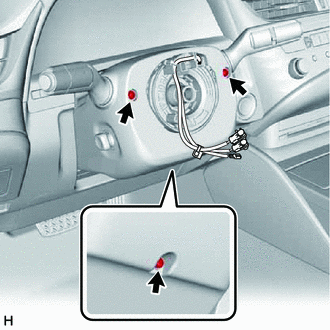
.png) | Push Area |
.png) | Push in this direction |
(b) While pressing the push area shown in the illustration to disengage the 2 claws, slightly lower the lower steering column cover sub-assembly.
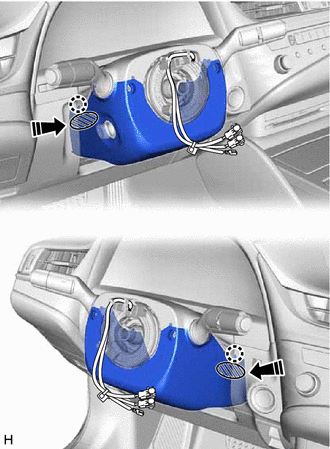
7. REMOVE UPPER STEERING COLUMN COVER
(a) Disengage the claw and separate the upper steering column cover.
.png)
| | Separate in this direction |
| (b) Disengage the 2 claws and 4 clips to remove the upper steering column cover. |
|
.png)
8. REMOVE TURN SIGNAL SWITCH ASSEMBLY WITH SPIRAL CABLE SUB-ASSEMBLY
NOTICE:
- Do not remove/install the spiral cable with sensor sub-assembly with the auxiliary battery connected and the engine switch (for Gasoline Model) or power switch (for HV Model) on (IG).
- Do not rotate the spiral cable with sensor sub-assembly without the steering wheel assembly installed, with the auxiliary battery connected and the engine switch (for Gasoline Model) or power switch (for HV Model) on (IG).
- Ensure that the steering wheel assembly is installed and aligned straight when inspecting the steering sensor.
(a) Disconnect each connector from the turn signal switch assembly with spiral cable sub-assembly.
| (b) Using pliers, expand the clamp. |
|
.png)
(c) While holding the clamp expanded, raise the claw using a screwdriver to disengage it, and then remove the turn signal switch assembly with spiral cable sub-assembly from the steering column assembly.
9. REMOVE LOWER NO. 1 INSTRUMENT PANEL AIRBAG ASSEMBLY
Click here
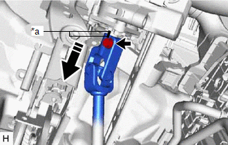
10. REMOVE NO. 1 AIR DUCT SUB-ASSEMBLY
(a) Remove the 2 bolts.
.png)
| *a | View A |
.png) | Front |
(b) Disengage the 3 claws to remove the No. 1 air duct sub-assembly.
NOTICE:
Be careful not to deform or damage the lower heater case of the air conditioner unit assembly when removing the No. 1 air duct sub-assembly.
11. REMOVE FRONT WHEEL LH
Click here
12. SEPARATE STEERING INTERMEDIATE SHAFT ASSEMBLY
Click here
13. REMOVE STEERING COLUMN HOLE COVER
(a) Turn back the floor carpet.
| (b) Remove the clip. |
|
.png)
(c) Disengage the 2 clips to remove the steering column hole cover.
14. REMOVE STEERING INTERMEDIATE SHAFT ASSEMBLY
| (a) Using a screwdriver, loosen the clamp as shown in the illustration. |
|
.png)
(b) Remove the bolt and slide the steering intermediate shaft assembly.
NOTICE:
Do not remove the steering intermediate shaft assembly from the steering column assembly.
| *a | Matchmark |
| | Slide in this direction |
(c) Put matchmarks on the steering intermediate shaft assembly and steering column assembly.
(d) Remove the steering intermediate shaft assembly from the steering column assembly.
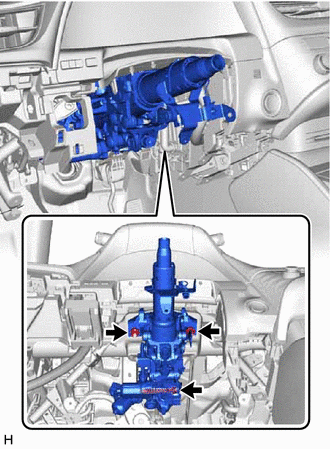
15. REMOVE STEERING COLUMN ASSEMBLY
(a) Disconnect each connector and disengage each wire harness clamp from the steering column assembly.
| (b) Remove the bolt, 2 nuts and steering column assembly. |
|
READ NEXT:
 Disassembly
DISASSEMBLY CAUTION / NOTICE / HINT NOTICE: Before replacing the steering lock actuator assembly, refer to Registration. for Gasoline Model: Click here for HV Model: Click here PROCEDURE 1. REM
Inspection
INSPECTION PROCEDURE 1. INSPECT STEERING COLUMN ASSEMBLY (a) Check that the 2 bushings are securely installed to the steering column assembly. HINT: If the bushings are deformed, missing or damaged
Reassembly
REASSEMBLY PROCEDURE 1. INSTALL MULTIPLEX TILT AND TELESCOPIC ECU Install in this direction (a) Engage the 2 claws to install the multiplex tilt and telescopic ECU. 2. INSTALL STEERING LOCK
SEE MORE:
Lost Communication with Wiper System LIN BUS (B1373)
DESCRIPTION The main body ECU (multiplex network body ECU) and windshield wiper motor assembly communicate via LIN communication. The main body ECU (multiplex network body ECU) stores this DTC if communication becomes abnormal. DTC No. Detection Item DTC Detection Condition Trouble Area M
Components
COMPONENTS ILLUSTRATION *1 COURTESY LIGHT ASSEMBLY *2 REAR DOOR ARMREST COVER *3 REAR DOOR INSIDE HANDLE SUB-ASSEMBLY *4 REAR DOOR TRIM BOARD SUB-ASSEMBLY *5 REAR DOOR TRIM UPPER PAD *6 REAR POWER WINDOW REGULATOR SWITCH ASSEMBLY WITH REAR DOOR UPPER ARMREST BASE PANEL
