
Lexus ES: Removal
REMOVAL
CAUTION / NOTICE / HINT
The necessary procedures (adjustment, calibration, initialization or registration) that must be performed after parts are removed and installed, or replaced during heated steering wheel controller (steering vibration ECU) removal/installation are shown below.
Necessary Procedures After Parts Removed/Installed/Replaced (for Gasoline Model)| Replaced Part or Performed Procedure | Necessary Procedure | Effect/Inoperative Function when Necessary Procedure not Performed | Link |
|---|---|---|---|
|
*: When performing learning using the Techstream.
Click here | |||
| Disconnect cable from negative auxiliary battery terminal | Perform steering sensor zero point calibration | Lane Control System | |
| Pre-collision System | |||
| Parking Support Brake System* | |||
| Lighting System | |||
| Memorize steering angle neutral point | Parking Assist Monitor System | | |
| Panoramic View Monitor System | | ||
| Initialize power trunk lid system | Power Trunk Lid System | | |
| Replaced Part or Performed Procedure | Necessary Procedure | Effect/Inoperative Function when Necessary Procedure not Performed | Link |
|---|---|---|---|
|
*: When performing learning using the Techstream.
Click here | |||
| Disconnect cable from negative auxiliary battery terminal | Perform steering sensor zero point calibration | Lane Control System | |
| Pre-collision System | |||
| Parking Support Brake System* | |||
| Lighting System | |||
| Memorize steering angle neutral point | Parking Assist Monitor System | | |
| Panoramic View Monitor System | | ||
| Initialize power trunk lid system | Power Trunk Lid System | | |
NOTICE:
for Gasoline Model:- After the engine switch is turned off, the radio receiver assembly records various types of memory and settings. As a result, after turning the engine switch off, make sure to wait at least 85 seconds before disconnecting the cable from the negative (-) battery terminal. (for Audio and Visual System)
- After the engine switch is turned off, the radio receiver assembly records various types of memory and settings. As a result, after turning the engine switch off, make sure to wait at least 85 seconds before disconnecting the cable from the negative (-) battery terminal. (for Navigation System)
- After the power switch is turned off, the radio receiver assembly records various types of memory and settings. As a result, after turning the power switch off, make sure to wait at least 85 seconds before disconnecting the cable from the negative (-) auxiliary battery terminal. (for Audio and Visual System)
- After the power switch is turned off, the radio receiver assembly records various types of memory and settings. As a result, after turning the power switch off, make sure to wait at least 85 seconds before disconnecting the cable from the negative (-) auxiliary battery terminal. (for Navigation System)
PROCEDURE
1. REMOVE HORN BUTTON ASSEMBLY
Click here .gif)
2. REMOVE HEATED STEERING WHEEL CONTROLLER (STEERING VIBRATION ECU)
(a) Disconnect the spiral cable connector from the heated steering wheel controller (steering vibration ECU).
| (b) Remove the 2 screws. |
|
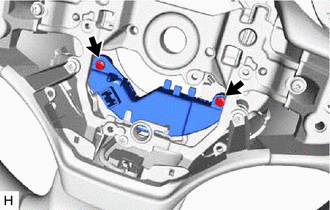
(c) Disconnect the connector to remove the heated steering wheel controller (steering vibration ECU) and steering wheel pad bracket.
NOTICE:
- Work carefully so that the heater thermistor does not come off the lower steering wheel boss cover.
- If the heater thermistor comes off the lower steering wheel boss cover, replace the steering wheel assembly.
READ NEXT:
 Installation
INSTALLATION PROCEDURE 1. INSTALL HEATED STEERING WHEEL CONTROLLER (STEERING VIBRATION ECU) (a) Connect the connector to the heated steering wheel controller (steering vibration ECU). (b) Install t
Precaution
PRECAUTION PRECAUTION FOR DISCONNECTING CABLE FROM NEGATIVE BATTERY TERMINAL NOTICE: When disconnecting the cable from the negative (-) battery terminal, initialize the following system(s) after the c
SEE MORE:
Open or Short in Front Speed Sensor RH Circuit (C1405,C1406)
DESCRIPTION Refer to DTCs C1413 and C1414. Click here DTC No. Detection Item INF Code DTC Detection Condition Trouble Area MIL Note C1405 Open or Short in Front Speed Sensor RH Circuit 503 506 508
INF Code: 503
An open in the speed sensor signal circuit continues for
Installation
INSTALLATION CAUTION / NOTICE / HINT HINT:
Use the same procedure for the RH side and LH side.
The following procedure is for the LH side.
PROCEDURE 1. INSTALL WASHER NOZZLE SUB-ASSEMBLY (a) Connect a new washer nozzle sub-assembly to the washer hose. (b) Engage the 2 claws as indicated by t
