Lexus ES: Rear Speed Sensor (for Awd)
Components
COMPONENTS
ILLUSTRATION
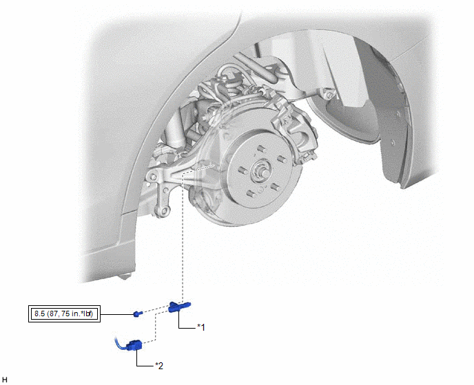
| *1 | REAR SKID CONTROL SENSOR | *2 | NO. 2 PARKING BRAKE WIRE ASSEMBLY |
.png) | Tightening torque for "Major areas involving basic vehicle performance such as moving/turning/stopping": N*m (kgf*cm, ft.*lbf) | - | - |
Installation
INSTALLATION
CAUTION / NOTICE / HINT
HINT:
- Use the same procedure for the RH side and LH side.
- The following procedure is for the LH side.
PROCEDURE
1. INSTALL REAR SKID CONTROL SENSOR
(a) Install the rear skid control sensor to the rear axle carrier sub-assembly with the bolt.
Torque:
8.5 N·m {87 kgf·cm, 75 in·lbf}
NOTICE:
- Keep the tip of the rear skid control sensor and installation hole free of foreign matter.
- Firmly insert the rear skid control sensor body into the rear axle carrier sub-assembly before tightening the bolt.
- After installing the rear skid control sensor to the rear axle carrier sub-assembly, make sure that there is no clearance between the rear skid control sensor stay and rear axle carrier sub-assembly. Also make sure that no foreign matter is stuck between the parts.
(b) Connect the No. 2 parking brake wire assembly connector to the rear skid control sensor.
2. INSTALL REAR WHEEL
Click here .gif)
3. CHECK FOR SPEED SENSOR SIGNAL
Click here
Removal
REMOVAL
CAUTION / NOTICE / HINT
HINT:
- Use the same procedure for the RH side and LH side.
- The following procedure is for the LH side.
PROCEDURE
1. REMOVE REAR WHEEL
Click here .gif)
2. REMOVE REAR SKID CONTROL SENSOR
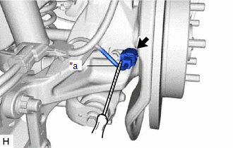
| (a) Using a screwdriver with its tip wrapped with protective tape, disconnect the No. 2 parking brake wire assembly connector from the rear skid control sensor. NOTICE:
|
|
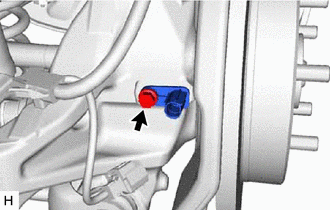
| (b) Remove the bolt and the rear skid control sensor from the rear axle carrier sub-assembly. NOTICE:
|
|
READ NEXT:
 Components
COMPONENTS ILLUSTRATION *1 NO. 2 PARKING BRAKE WIRE ASSEMBLY *2 REAR AXLE HUB AND BEARING ASSEMBLY *3 REAR DISC *4 REAR DISC BRAKE CALIPER ASSEMBLY *5 REAR FLEXIBLE HOSE *6
Installation
INSTALLATION CAUTION / NOTICE / HINT for HV Model:
When removing or installing the rear disc brake caliper assembly, pushing back the disc brake piston may cause a large clearance between the brake
SEE MORE:
Customize Parameters
CUSTOMIZE PARAMETERS CUSTOMIZE ADAPTIVE VARIABLE SUSPENSION SYSTEM HINT: "Custom" mode can be selected by using the drive mode select switch (combination switch assembly). (a) Customizing with the multi-display (1) Turn the engine switch on (IG). (2) Enter the following menus: MENU / Setup / Vehicle
Removal
REMOVAL CAUTION / NOTICE / HINT The necessary procedures (adjustment, calibration, initialization or registration) that must be performed after parts are removed and installed, or replaced during tire pressure warning valve and transmitter removal/installation are shown below. Necessary Procedures A
