Lexus ES: Removal
REMOVAL
CAUTION / NOTICE / HINT
The necessary procedures (adjustment, calibration, initialization, or registration) that must be performed after parts are removed and installed, or replaced during central gateway ECU (network gateway ECU) removal/installation are shown below.
Necessary Procedure After Parts Removed/Installed/Replaced (for Gasoline Model)| Replaced Part or Performed Procedure | Necessary Procedure | Effect/Inoperative Function when Necessary Procedure not Performed | Link |
|---|---|---|---|
|
*: When performing learning using the Techstream.
Click here | |||
| Disconnect cable from negative battery terminal | Perform steering sensor zero point calibration | Lane Control System (for Gasoline Model) | |
| Pre-collision System (for Gasoline Model) | |||
| Parking Support Brake System (for Gasoline Model)* | |||
| Lighting System (for Gasoline Model) | |||
| Memorize steering angle neutral point | Parking Assist Monitor System (for Gasoline Model) | | |
| Panoramic View Monitor System (for Gasoline Model) | | ||
| Initialize power trunk lid system | Power Trunk Lid System (for Gasoline Model) | | |
CAUTION:
Some of these service operations affect the SRS airbag system. Read the precautionary notices concerning the SRS airbag system before servicing.
.png)
Click here .gif)
NOTICE:
- After the engine switch is turned off, the radio receiver assembly records various types of memory and settings. As a result, after turning the engine switch off, make sure to wait at least 85 seconds before disconnecting the cable from the negative (-) battery terminal. (for Audio and Visual System)
- After the engine switch is turned off, the radio receiver assembly records various types of memory and settings. As a result, after turning the engine switch off, make sure to wait at least 85 seconds before disconnecting the cable from the negative (-) battery terminal. (for Navigation System)
| Replaced Part or Performed Procedure | Necessary Procedure | Effect/Inoperative Function When Necessary Procedures are not Performed | Link |
|---|---|---|---|
|
*: When performing learning using the Techstream.
Click here | |||
| Disconnect cable from negative auxiliary battery terminal | Perform steering sensor zero point calibration | Lane Control System (for HV Model) | |
| Pre-collision System (for HV Model) | |||
| Parking Support Brake System (for HV Model)* | |||
| Lighting System (for HV Model) | |||
| Memorize steering angle neutral point | Parking Assist Monitor System (for HV Model) | | |
| Panoramic View Monitor System (for HV Model) | | ||
| Initialize power trunk lid system | Power Trunk Lid System (for HV Model) | | |
CAUTION:
Some of these service operations affect the SRS airbag system. Read the precautionary notices concerning the SRS airbag system before servicing.
Click here
NOTICE:
- After the power switch is turned off, the radio receiver assembly records various types of memory and settings. As a result, after turning the power switch off, make sure to wait at least 85 seconds before disconnecting the cable from the negative (-) auxiliary battery terminal. (for Audio and Visual System)
- After the power switch is turned off, the radio receiver assembly records various types of memory and settings. As a result, after turning the power switch off, make sure to wait at least 85 seconds before disconnecting the cable from the negative (-) auxiliary battery terminal. (for Navigation System)
PROCEDURE
1. REMOVE LOWER NO. 2 INSTRUMENT PANEL AIRBAG ASSEMBLY
Click here
2. REMOVE GLOVE COMPARTMENT DOOR ASSEMBLY
Click here
3. REMOVE ECU INTEGRATION BOX RH
(a) Disconnect each connector.
(b) Disengage the 2 clamps.
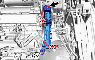
.png) | Nut |
 | Bolt |
(c) Remove the nut, bolt and ECU integration box RH.
4. REMOVE CENTRAL GATEWAY ECU (NETWORK GATEWAY ECU)
(a) Disengage the 2 claws and remove the central gateway ECU (network gateway ECU) as shown in the illustration.
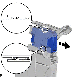
.png) | Remove in this Direction |
NOTICE:
- If the ECU integration box is deformed or damaged, replace it.
- Do not bend the 2 claws more than necessary.
READ NEXT:
 Components
COMPONENTS ILLUSTRATION *1 CENTRAL GATEWAY ECU (NETWORK GATEWAY ECU) *2 ECU INTEGRATION BOX RH *3 GLOVE COMPARTMENT DOOR ASSEMBLY - -
Lost Communication with Power Source Control (B278C)
DESCRIPTION When an internal malfunction is detected in the certification ECU (smart key ECU assembly), this DTC is stored. DTC No. Detection Item DTC Detection Condition Trouble Area B27
SEE MORE:
Disassembly
DISASSEMBLY PROCEDURE 1. REMOVE OIL PUMP RELIEF VALVE (a) Using a 27 mm socket wrench, remove the oil pump relief valve plug from the oil pump cover sub-assembly. *1 Oil Pump Relief Valve *2 Oil Pump Relief Valve Spring *3 Oil Pump Relief Valve Plug (b) Remove
EVAP System
RELATED DTCS DTC No. SAE Monitoring Item Link P00FE00 P00FE EVAP vent line blocked P043E00 P043E Reference orifice clogged (built into canister pump module) P043F00 P043F Reference orifice high-flow (built into canister pump module) P04417E P0441 Pu
