Lexus ES: Removal
REMOVAL
CAUTION / NOTICE / HINT
The necessary procedures (adjustment, calibration, initialization or registration) that must be performed after parts are removed and installed, or replaced during fuel tank assembly removal/installation are shown below.
Necessary Procedures After Parts Removed/Installed/Replaced| Replaced Part or Performed Procedure | Necessary Procedure | Effect/Inoperative Function when Necessary Procedure not Performed | Link |
|---|---|---|---|
|
*: When performing learning using the Techstream.
Click here | |||
| Battery terminal is disconnected/reconnected | Perform steering sensor zero point calibration | Lane Control System (for Gasoline Model) | |
| Pre-collision System (for Gasoline Model) | |||
| Parking Support Brake System (for Gasoline Model)* | |||
| Lighting System (for Gasoline Model) | |||
| Memorize steering angle neutral point | Parking Assist Monitor System (for Gasoline Model) | | |
| Panoramic View Monitor System (for Gasoline Model) | | ||
| Initialize power trunk lid system | Power Trunk Lid System (for Gasoline Model) | | |
| Gas leak from exhaust system is repaired | Inspection after repair |
| |
CAUTION:
-
Never perform work on fuel system components near any possible ignition sources.
.png)
- Vaporized fuel could ignite, resulting in a serious accident.
-
Do not perform work on fuel system components without first disconnecting the cable from the negative (-) battery terminal.
.png)
- Sparks could cause vaporized fuel to ignite, resulting in a serious accident.
-
The fuel tank assembly is very heavy. Be sure to follow the procedure described in the repair manual, or the fuel tank assembly may fall off the engine lifter.
.png)
NOTICE:
- After the engine switch is turned off, the radio receiver assembly records various types of memory and settings. As a result, after turning the engine switch off, make sure to wait at least 85 seconds before disconnecting the cable from the negative (-) battery terminal. (for Audio and Visual System)
- After the engine switch is turned off, the radio receiver assembly records various types of memory and settings. As a result, after turning the engine switch off, make sure to wait at least 85 seconds before disconnecting the cable from the negative (-) battery terminal. (for Navigation System)
PROCEDURE
1. REMOVE FUEL SUCTION TUBE WITH PUMP AND GAUGE ASSEMBLY
Click here .gif)
2. DRAIN FUEL
3. REMOVE CENTER EXHAUST PIPE ASSEMBLY
Click here
4. REMOVE NO. 2 FLOOR UNDER COVER
Click here
5. REMOVE NO. 1 FLOOR UNDER COVER
Click here
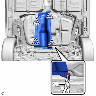
6. REMOVE NO. 1 FUEL TANK PROTECTOR
| (a) Using needle nose pliers, remove the 4 clips and No. 1 fuel tank protector from the fuel tank assembly. |
|
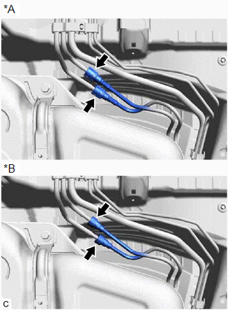
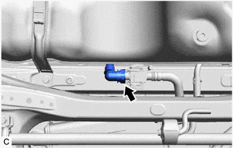
7. DISCONNECT FUEL TANK MAIN TUBE SUB-ASSEMBLY
| (a) Disconnect the fuel tank main tube sub-assembly from the fuel pipe. Click here |
|
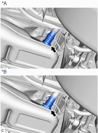
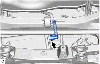
8. DISCONNECT FUEL TANK TO FILLER PIPE HOSE
| (a) Disconnect the fuel tank to filler pipe hose from the fuel tank assembly. Click here |
|
9. REMOVE FUEL TANK ASSEMBLY
CAUTION:
The fuel tank assembly is very heavy. Be sure to follow the procedure described in the repair manual, or the fuel tank assembly may fall off the engine lifter.
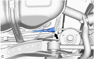
| (a) Disconnect the fuel tank breather tube sub-assembly from the fuel pipe. Click here |
|
(b) w/ Fuel Outlet Valve Assembly:
| (1) Disconnect the fuel cut off valve with tube assembly from the fuel outlet valve assembly. Click here |
|
(c) w/o Fuel Outlet Valve Assembly:
| (1) Disconnect the fuel cut off valve with tube assembly from the canister (charcoal canister assembly). Click here |
|
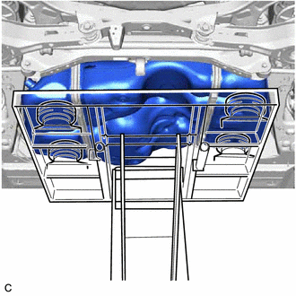
| (d) Support the fuel tank assembly using an engine lifter. HINT: Using height adjustment attachments and plate lift attachments, keep the fuel tank assembly horizontal. |
|
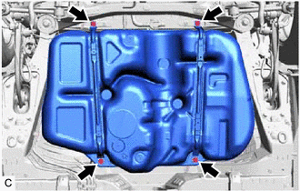
| (e) Remove the 4 bolts, No. 1 fuel tank band sub-assembly LH and No. 1 fuel tank band sub-assembly RH. |
|
(f) Lower the engine lifter to remove the fuel tank assembly.
NOTICE:
- Be careful not to drop the fuel tank assembly.
- When removing the fuel tank assembly, tilt it slightly to prevent it from interfering with the surrounding parts.
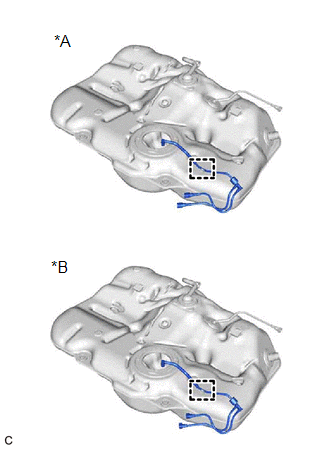
10. REMOVE FUEL TANK MAIN TUBE SUB-ASSEMBLY
| (a) Disengage the clamp to remove the fuel tank main tube sub-assembly from the fuel tank assembly. |
|
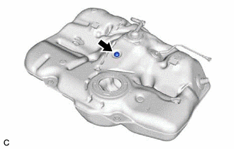
11. REMOVE NO. 2 FUEL TANK CUSHION (for TMMK Made)
| (a) Remove the No. 2 fuel tank cushion from the fuel tank assembly. |
|
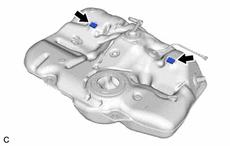
12. REMOVE NO. 1 FUEL TANK CUSHION (for TMMK Made)
| (a) Remove the 2 No. 1 fuel tank cushions from the fuel tank assembly. |
|
READ NEXT:
 Installation
INSTALLATION PROCEDURE 1. INSTALL NO. 1 FUEL TANK CUSHION (for TMMK Made) (a) Install 2 new No. 1 fuel tank cushions to the fuel tank assembly. 2. INSTALL NO. 2 FUEL TANK CUSHION (for TMMK Made) (a) I
Air Cleaner Filter Element
ComponentsCOMPONENTS ILLUSTRATION *1 AIR CLEANER CAP SUB-ASSEMBLY *2 AIR CLEANER FILTER ELEMENT SUB-ASSEMBLY RemovalREMOVAL PROCEDURE 1. SEPARATE AIR CLEANER CAP SUB-ASSEMBLY Click here
SEE MORE:
System Diagram
SYSTEM DIAGRAM Communication Table Transmitting ECU Receiving ECU Signal Communication Method Multiplex Network Master Switch Assembly Power Window Regulator Motor Assembly (for Driver Door) Power window auto up and down signal LIN
Power Window Regulator Motor Assembly (
On-vehicle Inspection
ON-VEHICLE INSPECTION PROCEDURE 1. FUEL PUMP ASSEMBLY OPERATION (a) Check fuel pressure. (1) Connect the Techstream to the DLC3. (2) Start the engine. (3) Turn the Techstream on. (4) Enter the following menus: Powertrain / Engine / Active Test / Control the Target Fuel Pressure Offset. Powertrain &g
