Lexus ES: Installation
INSTALLATION
PROCEDURE
1. INSTALL NO. 1 FUEL TANK CUSHION (for TMMK Made)
(a) Install 2 new No. 1 fuel tank cushions to the fuel tank assembly.
2. INSTALL NO. 2 FUEL TANK CUSHION (for TMMK Made)
(a) Install a new No. 2 fuel tank cushion to the fuel tank assembly.
3. INSTALL FUEL TANK MAIN TUBE SUB-ASSEMBLY
(a) Engage the clamp to install the fuel tank main tube sub-assembly to the fuel tank assembly.
4. INSTALL FUEL TANK ASSEMBLY
CAUTION:
The fuel tank assembly is very heavy. Be sure to follow the procedure described in the repair manual, or the fuel tank assembly may fall off the engine lifter.
.png)
(a) Set the fuel tank assembly on an engine lifter.
NOTICE:
Using height adjustment attachments and plate lift attachments, keep the fuel tank assembly horizontal.
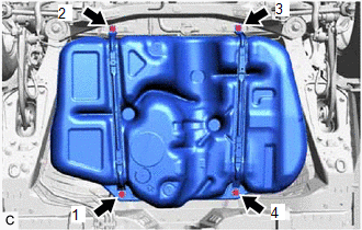
| (b) Using the engine lifter, slowly raise the fuel tank assembly, and then install the fuel tank assembly, No. 1 fuel tank band sub-assembly LH and No. 1 fuel tank band sub-assembly RH with the 4 bolts in the order shown in the illustration. Torque: 45 N·m {459 kgf·cm, 33 ft·lbf} NOTICE:
|
|
(c) w/ Fuel Outlet Valve Assembly:
(1) Connect the fuel cut off valve with tube assembly to the fuel outlet valve assembly.
Click here .gif)
(d) w/o Fuel Outlet Valve Assembly:
(1) Connect the fuel cut off valve with tube assembly to the canister (charcoal canister assembly).
Click here
(e) Connect the fuel tank breather tube sub-assembly to the fuel pipe.
Click here
5. CONNECT FUEL TANK TO FILLER PIPE HOSE
(a) Connect the fuel tank to filler pipe hose to the fuel tank assembly.
Click here
6. CONNECT FUEL TANK MAIN TUBE SUB-ASSEMBLY
(a) Connect the fuel tank main tube sub-assembly to the fuel pipe.
Click here
7. INSTALL NO. 1 FUEL TANK PROTECTOR
(a) Install the No. 1 fuel tank protector to the fuel tank assembly with the 4 clips.
8. INSTALL NO. 1 FLOOR UNDER COVER
Click here
9. INSTALL NO. 2 FLOOR UNDER COVER
Click here
10. INSTALL CENTER EXHAUST PIPE ASSEMBLY
Click here
11. INSTALL FUEL SUCTION TUBE WITH PUMP AND GAUGE ASSEMBLY
Click here
12. ADD FUEL
READ NEXT:
 Air Cleaner Filter Element
ComponentsCOMPONENTS ILLUSTRATION *1 AIR CLEANER CAP SUB-ASSEMBLY *2 AIR CLEANER FILTER ELEMENT SUB-ASSEMBLY RemovalREMOVAL PROCEDURE 1. SEPARATE AIR CLEANER CAP SUB-ASSEMBLY Click here
SEE MORE:
Slip Indicator Light does not Come ON
DESCRIPTION The skid control ECU (brake actuator assembly) controls the slip indicator light in the combination meter assembly via CAN communication. CAUTION / NOTICE / HINT NOTICE: After replacing the skid control ECU (brake actuator assembly), perform acceleration sensor zero point calibration and
Start Up Signal Circuit between Radio Receiver Assembly and Navigation ECU
DESCRIPTION This circuit includes the navigation ECU and radio receiver assembly. WIRING DIAGRAM PROCEDURE 1. CHECK HARNESS AND CONNECTOR (RADIO RECEIVER ASSEMBLY - NAVIGATION ECU) (a) Disconnect the G1 radio receiver assembly connector. (b) Disconnect the G14 navigation ECU connector. (c)
