Lexus ES: Removal
REMOVAL
CAUTION / NOTICE / HINT
The necessary procedures (adjustment, calibration, initialization, or registration) that must be performed after parts are removed and installed, or replaced during rear disc brake pad removal/installation are shown below.
Necessary Procedures After Parts Removed/Installed/Replaced (for HV Model)|
Replaced Part or Performed Procedure |
Necessary Procedure |
Effect/Inoperative Function when Necessary Procedure not Performed |
Link |
|---|---|---|---|
| *: When performing learning using the Techstream.
Click here |
|||
|
Auxiliary battery terminal is disconnected/reconnected |
Perform steering sensor zero point calibration |
Lane Control System (for HV Model) |
|
|
Pre-collision System (for HV Model) |
|||
|
Parking Support Brake System (for HV Model)* |
|||
|
Lighting System (for HV Model) |
|||
|
Memorize steering angle neutral point |
Parking Assist Monitor System (for HV Model) |
|
|
|
Panoramic View Monitor System (for HV Model) |
|
||
|
Initialize power trunk lid system |
Power Trunk Lid System (for HV Model) |
|
|
NOTICE:
- Immediately after installing the brake pads, the braking performance may be reduced. Always perform a road test in a safe place while paying attention to the surroundings.
- After replacing the rear disc brake pads, the brake pedal may feel soft due to clearance between the rear disc brake pads and rear disc. Depress the brake pedal several times until the brake pedal feels firm.
- After replacing the rear disc brake pads, always perform a road test to check the braking performance and check for vibrations.
- When the brake pedal is first depressed after replacing the brake pads or pushing back the disc brake piston, DTC C1214 may be stored. As there is no malfunction, clear the DTC. (for HV Model)
- While the auxiliary battery is connected, even if the power switch is off, the brake control system activates when the brake pedal is depressed or any door courtesy switch turns on. Therefore, when servicing the brake system components, do not operate the brake pedal or open/close the doors while the auxiliary battery is connected. (for HV Model)
- After the power switch is turned off, the radio receiver assembly records various types of memory and settings. As a result, after turning the power switch off, make sure to wait at least 85 seconds before disconnecting the cable from the negative (-) auxiliary battery terminal. (for HV Model Audio and Visual System)
- After the power switch is turned off, the radio receiver assembly records various types of memory and settings. As a result, after turning the power switch off, make sure to wait at least 85 seconds before disconnecting the cable from the negative (-) auxiliary battery terminal. (for HV Model Navigation System)
HINT:
- Use the same procedure for the RH side and LH side.
- The following procedure is for the LH side.
PROCEDURE
1. PRECAUTION (for HV Model)
NOTICE:
- After turning the power switch off, waiting time may be required before disconnecting the cable from the negative (-) auxiliary battery terminal. Therefore, make sure to read the disconnecting the cable from the negative (-) auxiliary battery terminal notices before proceeding with work.
- Make sure to read the precautions of the electric parking brake system
before removing the rear brake assembly.
Click here
.gif)
2. REMOVE REAR WHEEL
Click here
3. PERFORM REAR BRAKE PAD REPLACEMENT MODE
for Gasoline Model: Click here
for HV Model: Click here
4. DISABLE BRAKE CONTROL (for HV Model)
Click here
5. DISCONNECT NO. 2 PARKING BRAKE WIRE ASSEMBLY
Click here
6. REMOVE REAR DISC BRAKE PAD
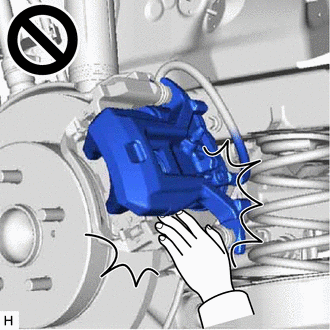
CAUTION:
- Be careful not to get pinched by the rear disc brake cylinder assembly or other parts when removing the rear disc brake pads.
- After lifting up the rear disc brake cylinder assembly, secure it in place before performing any work on it.
- The rear disc brake cylinder assembly could fall, pinching hands or fingers and causing injury.
|
(a) Hold the rear No. 1 disc brake cylinder slide pin and remove the bolt. |
|
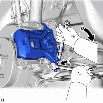
(b) Pull the rear disc brake cylinder assembly upward.
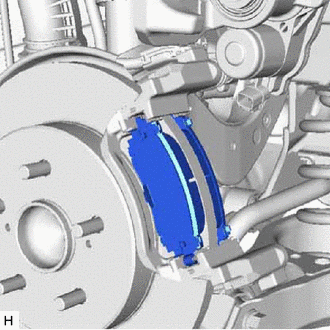
|
(c) Remove the 2 rear disc brake pads from the rear disc brake cylinder mounting. |
|
7. REMOVE REAR DISC BRAKE ANTI-SQUEAL SHIM KIT
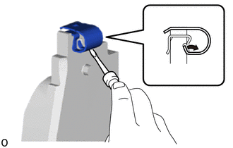
|
(a) Remove the rear No. 2 disc brake anti-squeal shim from the rear disc brake pad (inside). |
|

(b) Remove the rear No. 1 disc brake anti-squeal shim from the rear disc brake pad (inside).
(c) Remove the rear disc brake anti-squeal shim from the rear disc brake pad (outside).
|
(d) Remove the rear disc brake pad wear indicator plate from each rear disc brake pad. |
|
READ NEXT:
 Installation
INSTALLATION
CAUTION / NOTICE / HINT
NOTICE:
Immediately after installing the brake pads, the braking performance
may be reduced. Always perform a road test in a safe place while paying
Tire And Wheel
Removal
REMOVAL
PROCEDURE
1. REMOVE WHEEL ASSEMBLY
(a) Loosen the axle hub nuts approximately 90°.
(b) Lift up the vehicle and remove the axle hub nuts and wheel assembly.
Installation
INS
Transmitter Battery
Components
COMPONENTS
ILLUSTRATION
*1
TRANSMITTER BATTERY
*2
MECHANICAL KEY
*3
TRANSMITTER HOUSING COVER
*4
SEE MORE:
Key-off Operation Function Operates even if Operating Conditions are not Satisfied
DESCRIPTION The sliding roof ECU (sliding roof drive gear sub-assembly) operates its built-in motor according to the sliding roof switch (map light sub-assembly) operation. Using the sliding roof switch (map light sub-assembly), if the sliding roof can be operated normally when 45 seconds or more ha
Parts Location
PARTS LOCATION ILLUSTRATION *1 ECM *2 FUEL TANK ASSEMBLY *3 FUEL PUMP CONTROL ECU *4 FUEL SUCTION TUBE WITH PUMP AND GAUGE ASSEMBLY - FUEL PUMP (for Low Pressure) - FUEL SENDER GAUGE ASSEMBLY - FUEL MAIN VALVE ASSEMBLY (for Low Pressure) - FUEL MAIN VALVE ASSEMBLY (for High Press
