Lexus ES: Tire And Wheel
Removal
REMOVAL
PROCEDURE
1. REMOVE WHEEL ASSEMBLY
(a) Loosen the axle hub nuts approximately 90°.
(b) Lift up the vehicle and remove the axle hub nuts and wheel assembly.
Installation
INSTALLATION
PROCEDURE
1. INSTALL WHEEL ASSEMBLY
NOTICE:
- Only use axle hub nuts that are compatible with the wheel. If incompatible axle hub nuts are used, the contact surface of the wheel and axle hub nut may become deformed or damaged. This may result in looseness or loss of one or more axle hub nuts, even if they are tightened to the correct torque.
- Check that there is no foreign matter or rust on the axle hub bolts and the contact surfaces of the wheel, brake disc, axle hub, etc. Clean the contact surfaces and axle hub bolts if necessary. If a wheel assembly is installed with foreign matter or rust between the contact surfaces, the foreign matter or rust may work loose. This may result in looseness or loss of one or more axle hub nuts, even if they are tightened to the correct torque.
- When installing the axle hub nuts, clean the axle hub bolts with non-residue solvent and check that the axle hub nuts rotate smoothly by hand. If the axle hub nuts do not rotate smoothly, check that there is no foreign matter or rust and clean if necessary. If the axle hub nuts still do not rotate smoothly, replace the axle hub nuts and axle hub bolts with new ones.
(a) While aligning the wheel assembly with the center of the axle hub, install the axle hub nuts by hand.
|
(b) Temporarily tighten the axle hub nuts in the order shown in the illustration. |
|
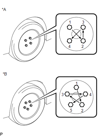
(c) Lower the vehicle then fully tighten the axle hub nuts in the order shown in the illustration.
Torque:
103 N·m {1050 kgf·cm, 76 ft·lbf}
READ NEXT:
 Transmitter Battery
Components
COMPONENTS
ILLUSTRATION
*1
TRANSMITTER BATTERY
*2
MECHANICAL KEY
*3
TRANSMITTER HOUSING COVER
*4
Components
COMPONENTS
ILLUSTRATION
*A
Type A
*B
Type B
*1
FRONT FENDER APRON SEAL LH
*2
FRONT WHEEL OPENING EXTEN
SEE MORE:
Terminals Of Ecu
TERMINALS OF ECU NOTICE:
DTCs may be output when connectors are disconnected during inspection. Therefore, be sure to clear the DTCs using the Techstream once the inspection has been completed.
Do not apply excessive force to the forward recognition camera connector.
CHECK FORWARD RECOGNITI
Hybrid/EV Battery Current Sensor "A" Circuit Range/Performance (P0ABF00)
DESCRIPTION A battery current sensor, which is mounted on the positive cable side of each HV battery junction block assembly, detects the current flowing to or from the battery pack. The battery current sensor sends a voltage, which varies between 0 and 5 V in proportion to the amperage, to the IB0
© 2016-2026 Copyright www.lexguide.net
