Lexus ES: Removal
REMOVAL
PROCEDURE
1. REMOVE FRONT WHEEL RH
Click here .gif)
2. REMOVE FRONT FENDER APRON SEAL RH
Click here
3. REMOVE V-BANK COVER SUB-ASSEMBLY
Click here
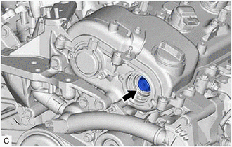
4. REMOVE CAMSHAFT TIMING OIL CONTROL SOLENOID ASSEMBLY (for Exhaust Side of Bank 2)
Click here
5. SET NO. 1 CYLINDER TO TDC/COMPRESSION
| (a) Turn the crankshaft pulley clockwise until its timing mark (cutout) is aligned with the timing mark on the timing chain cover assembly as shown in the illustration. |
|
.png)
| (b) Check that the cutout of the camshaft timing gear assembly is at the top. HINT: If the cutout of the camshaft timing gear assembly is not at the top, turn the crankshaft 360° clockwise and align the timing mark (cutout) of the crankshaft pulley with the timing mark on the timing chain cover assembly again. |
|

6. REMOVE CAMSHAFT TIMING GEAR BOLT
| (a) While holding the crankshaft pulley, remove the camshaft timing gear bolt. NOTICE:
|
|
READ NEXT:
 Inspection
INSPECTION PROCEDURE 1. INSPECT CAMSHAFT TIMING GEAR BOLT (a) Check the stroke of the plunger in the center of the camshaft timing gear bolt. Standard Stroke: 2.2 mm (0.0866 in.) or more HINT: Whe
Installation
INSTALLATION PROCEDURE 1. INSTALL CAMSHAFT TIMING GEAR BOLT (a) Make sure that the No. 1 cylinder is at TDC/compression. HINT: Check that the cutout of the camshaft timing gear assembly is at the top
SEE MORE:
Outside Air Temperature Sensor (C1652)
DESCRIPTION When a malfunction signal sent from the air conditioning system via CAN communication is detected by the clearance warning ECU assembly, DTC C1652 is stored. DTC No. Detection Item DTC Detection Condition Trouble Area C1652 Outside Air Temperature Sensor Ambient temperat
Key-off Operation Function Operates even if Operating Conditions are not Satisfied
DESCRIPTION When the front doors are closed, each power window regulator motor assembly can be operated for approximately 45 seconds after the engine switch is turned from on (IG) to off by receiving operation permission signals from the main body ECU (multiplex network body ECU). However, when appr
