Lexus ES: Removal
REMOVAL
CAUTION / NOTICE / HINT
The necessary procedures (adjustment, calibration, initialization or registration) that must be performed after parts are removed and installed, or replaced during camshaft timing oil control solenoid assembly removal/installation are shown below.
Necessary Procedures After Parts Removed/Installed/Replaced| Replaced Part or Performed Procedure | Necessary Procedure | Effect/Inoperative Function when Necessary Procedure not Performed | Link |
|---|---|---|---|
| Battery terminal is disconnected/reconnected | Perform steering sensor zero point calibration | Lane Control System | |
| Pre-collision System | |||
| Parking Support Brake System*1 | |||
| Lighting System | |||
| Memorize steering angle neutral point | Parking Assist Monitor System | | |
| Panoramic View Monitor System | | ||
| Initialize power trunk lid system | Power Trunk Lid System | | |
| Replacement of ECM | Vehicle Identification Number (VIN) registration | MIL comes on | |
| ECU communication ID registration (Immobiliser system) | Engine start function | | |
| Gas leak from exhaust system is repaired | Inspection after repair |
| |
| Replacement of ECM (If transaxle compensation code read from ECM) |
|
| for Initialization: for Registration: |
| Replacement of ECM (If transaxle compensation code not read from ECM) |
| ||
| Replacement of ECM | Code registration (Smart access system with push-button start (for Start Function, Gasoline Model) |
| |
| Replacement of automatic transaxle fluid | ATF thermal degradation estimate reset | The value of the Data List item "ATF Thermal Degradation Estimate" is not estimated correctly | |
| Suspension, tires, etc. (The vehicle height changes because of suspension or tire replacement) | Rear television camera assembly optical axis adjustment (Back camera position setting) | Parking assist monitor system | for Initialization: for Calibration: |
| Perform headlight ECU sub-assembly LH initialization | Lighting system | | |
| Front wheel alignment adjustment |
|
| |
| Front television camera view adjustment | Panoramic View Monitor System | for Initialization for Calibration |
| Replacement of front bumper assembly |
|
| |
-
*1: When performing learning using the Techstream.
Click here
.gif)
- *2: Not necessary when ECM replaced with new one
NOTICE:
- After the engine switch is turned off, the radio receiver assembly records various types of memory and settings. As a result, after turning the engine switch off, make sure to wait at least 85 seconds before disconnecting the cable from the negative (-) battery terminal. (for Audio and Visual System)
- After the engine switch is turned off, the radio receiver assembly records various types of memory and settings. As a result, after turning the engine switch off, make sure to wait at least 85 seconds before disconnecting the cable from the negative (-) battery terminal. (for Navigation System)
PROCEDURE
1. REMOVE V-BANK COVER SUB-ASSEMBLY
Click here
2. REMOVE CAMSHAFT TIMING OIL CONTROL SOLENOID ASSEMBLY (for Exhaust Side of Bank 2)
| (a) Disconnect the camshaft timing oil control solenoid assembly connector. |
|
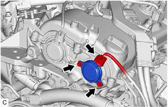
(b) Remove the 2 bolts and camshaft timing oil control solenoid assembly from the timing chain cover assembly.
NOTICE:
If the camshaft timing oil control solenoid assembly has been struck or dropped, replace it.
(c) Remove the O-ring from the camshaft timing oil control solenoid assembly.
NOTICE:
- If the O-ring comes off in the timing chain cover assembly, make sure to remove it.
- Do not drop the O-ring into the timing chain cover assembly.
3. REMOVE CAMSHAFT TIMING OIL CONTROL SOLENOID ASSEMBLY (for Intake Side of Bank 1)
| (a) Disconnect the camshaft timing oil control solenoid assembly connector. |
|
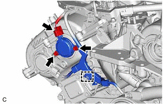
(b) Disengage the clamp to disconnect the engine wire.
(c) Remove the 2 bolts and camshaft timing oil control solenoid assembly from the timing chain cover assembly.
NOTICE:
If the camshaft timing oil control solenoid assembly has been struck or dropped, replace it.
(d) Remove the O-ring from the camshaft timing oil control solenoid assembly.
NOTICE:
- If the O-ring comes off in the timing chain cover assembly, make sure to remove it.
- Do not drop the O-ring into the timing chain cover assembly.
4. REMOVE FRONT FENDER APRON SEAL RH
Click here
5. REMOVE CAMSHAFT TIMING OIL CONTROL SOLENOID ASSEMBLY (for Exhaust Side of Bank 1)
| (a) Disconnect the camshaft timing oil control solenoid assembly connector. |
|
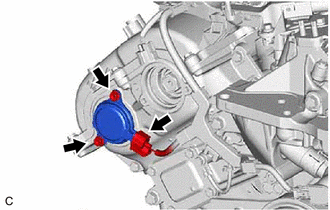
(b) Remove the 2 bolts and camshaft timing oil control solenoid assembly from the timing chain cover assembly.
NOTICE:
If the camshaft timing oil control solenoid assembly has been struck or dropped, replace it.
(c) Remove the O-ring from the camshaft timing oil control solenoid assembly.
NOTICE:
- If the O-ring comes off in the timing chain cover assembly, make sure to remove it.
- Do not drop the O-ring into the timing chain cover assembly.
6. REMOVE ENGINE ASSEMBLY WITH TRANSAXLE
Click here
7. REMOVE CAMSHAFT TIMING OIL CONTROL SOLENOID ASSEMBLY (for Intake Side of Bank 2)
| (a) Disconnect the camshaft timing oil control solenoid assembly connector. |
|
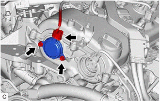
(b) Remove the 2 bolts and camshaft timing oil control solenoid assembly from the timing chain cover assembly.
NOTICE:
If the camshaft timing oil control solenoid assembly has been struck or dropped, replace it.
(c) Remove the O-ring from the camshaft timing oil control solenoid assembly.
NOTICE:
- If the O-ring comes off in the timing chain cover assembly, make sure to remove it.
- Do not drop the O-ring into the timing chain cover assembly.
READ NEXT:
 Inspection
INSPECTION PROCEDURE 1. INSPECT CAMSHAFT TIMING OIL CONTROL SOLENOID ASSEMBLY HINT: Use the same procedure for the intake side and exhaust side. (a) Check the resistance. (1) Measure the resistance
Installation
INSTALLATION PROCEDURE 1. INSTALL CAMSHAFT TIMING OIL CONTROL SOLENOID ASSEMBLY (for Intake Side of Bank 2) (a) Apply engine oil to a new O-ring and install it to the camshaft timing oil control so
SEE MORE:
Throttle / Pedal Position Sensor / Switch "A" Circuit Short to Battery or Open (P012015)
DESCRIPTION Refer to DTC P012011. Click here DTC No. Detection Item DTC Detection Condition Trouble Area MIL Memory Note P012015 Throttle / Pedal Position Sensor / Switch "A" Circuit Short to Battery or Open The output voltage of VTA1 is higher than 4.535 V for 2 seconds or
ABS Operates Before Necessary When Braking
DESCRIPTION Troubleshooting for when ABS operates too soon due to a noisy signal from the speed sensor, a difference in output, etc. PROCEDURE 1. PERFORM TEST MODE (SIGNAL CHECK) INSPECTION (SPEED SENSOR CIRCUIT) (a) Using the Techstream, perform a Test Mode (Signal Check) inspection sensor
