Lexus ES: Inspection
INSPECTION
PROCEDURE
1. INSPECT CAMSHAFT TIMING OIL CONTROL SOLENOID ASSEMBLY
HINT:
Use the same procedure for the intake side and exhaust side.
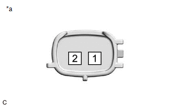
(a) Check the resistance.
| (1) Measure the resistance according to the value(s) in the table below. Standard Resistance:
If the result is not as specified, replace the camshaft timing oil control solenoid assembly. |
|
(b) Stroke Amount Inspection
| (1) Using vernier calipers, measure length (A) and (B) with the shaft of the camshaft timing oil control solenoid assembly set in the respective positions shown in the illustration. NOTICE: Do not apply battery voltage to the terminals of the camshaft timing oil control solenoid assembly. HINT: If the shaft does not extend under its own weight, extend the shaft with your fingers. |
|
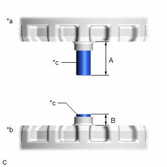
(2) Calculate the stroke amount based on the difference of length (A) and (B).
Standard:
6.5 mm (0.256 in.) or more
HINT:
Stroke amount = length (A) - length (B)
If the value is not as specified, replace the camshaft timing oil control solenoid assembly.
READ NEXT:
 Installation
INSTALLATION PROCEDURE 1. INSTALL CAMSHAFT TIMING OIL CONTROL SOLENOID ASSEMBLY (for Intake Side of Bank 2) (a) Apply engine oil to a new O-ring and install it to the camshaft timing oil control so
Components
COMPONENTS ILLUSTRATION *1 FRONT FENDER APRON SEAL RH *2 V-BANK COVER SUB-ASSEMBLY N*m (kgf*cm, ft.*lbf): Specified torque - - ILLUSTRATION *1 CAMSHAFT TIMING GEAR BOLT
SEE MORE:
Installation
INSTALLATION CAUTION / NOTICE / HINT HINT:
Use the same procedure for the RH side and LH side.
The following procedure is for the LH side.
PROCEDURE 1. PRECAUTION NOTICE: After turning the engine switch (for Gasoline Model) or power switch (for HV Model) off, waiting time may be required bef
Installation
INSTALLATION PROCEDURE 1. INSTALL FUEL SUCTION TUBE WITH PUMP AND GAUGE ASSEMBLY (a) Install a new fuel suction tube set gasket to the fuel tank assembly. (b) Connect the fuel return vent tube sub-assembly to the fuel suction tube with pump and gauge assembly. Click here NOTICE: When connecting th
