Lexus ES: Installation
INSTALLATION
PROCEDURE
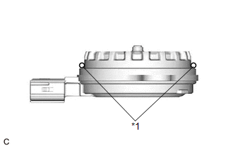
1. INSTALL CAMSHAFT TIMING OIL CONTROL SOLENOID ASSEMBLY (for Intake Side of Bank 2)
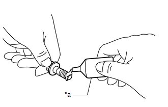
| (a) Apply engine oil to a new O-ring and install it to the camshaft timing oil control solenoid assembly as shown in the illustration. NOTICE: Do not damage the O-ring. |
|
| (b) Apply adhesive to 2 or 3 threads of 2 new bolts. Adhesive: Toyota Genuine Adhesive 1324, Three Bond 1324 or equivalent |
|
(c) Install the camshaft timing oil control solenoid assembly to the timing chain cover assembly with the 2 bolts.
Torque:
10 N·m {102 kgf·cm, 7 ft·lbf}
NOTICE:
- If the camshaft timing oil control solenoid assembly has been struck or dropped, replace it.
- Make sure that the O-ring is not cracked or moved out of place when installing the camshaft timing oil control solenoid assembly.
(d) Connect the camshaft timing oil control solenoid assembly connector.
2. INSTALL ENGINE ASSEMBLY WITH TRANSAXLE
Click here .gif)
3. INSTALL CAMSHAFT TIMING OIL CONTROL SOLENOID ASSEMBLY (for Exhaust Side of Bank 1)
| (a) Apply engine oil to a new O-ring and install it to the camshaft timing oil control solenoid assembly as shown in the illustration. NOTICE: Do not damage the O-ring. |
|
| (b) Apply adhesive to 2 or 3 threads of 2 new bolts. Adhesive: Toyota Genuine Adhesive 1324, Three Bond 1324 or equivalent |
|
(c) Install the camshaft timing oil control solenoid assembly to the timing chain cover assembly with the 2 bolts.
Torque:
10 N·m {102 kgf·cm, 7 ft·lbf}
NOTICE:
- If the camshaft timing oil control solenoid assembly has been struck or dropped, replace it.
- Make sure that the O-ring is not cracked or moved out of place when installing the camshaft timing oil control solenoid assembly.
(d) Connect the camshaft timing oil control solenoid assembly connector.
4. INSTALL FRONT FENDER APRON SEAL RH
Click here
5. INSTALL CAMSHAFT TIMING OIL CONTROL SOLENOID ASSEMBLY (for Intake Side of Bank 1)
| (a) Apply engine oil to a new O-ring and install it to the camshaft timing oil control solenoid assembly as shown in the illustration. NOTICE: Do not damage the O-ring. |
|
| (b) Apply adhesive to 2 or 3 threads of 2 new bolts. Adhesive: Toyota Genuine Adhesive 1324, Three Bond 1324 or equivalent |
|
(c) Install the camshaft timing oil control solenoid assembly to the timing chain cover assembly with the 2 bolts.
Torque:
10 N·m {102 kgf·cm, 7 ft·lbf}
NOTICE:
- If the camshaft timing oil control solenoid assembly has been struck or dropped, replace it.
- Make sure that the O-ring is not cracked or moved out of place when installing the camshaft timing oil control solenoid assembly.
(d) Engage the clamp to connect the engine wire.
(e) Connect the camshaft timing oil control solenoid assembly connector.
6. INSTALL CAMSHAFT TIMING OIL CONTROL SOLENOID ASSEMBLY (for Exhaust Side of Bank 2)
| (a) Apply engine oil to a new O-ring and install it to the camshaft timing oil control solenoid assembly as shown in the illustration. NOTICE: Do not damage the O-ring. |
|
| (b) Apply adhesive to 2 or 3 threads of 2 new bolts. Adhesive: Toyota Genuine Adhesive 1324, Three Bond 1324 or equivalent |
|
(c) Install the camshaft timing oil control solenoid assembly to the timing chain cover assembly with the 2 bolts.
Torque:
10 N·m {102 kgf·cm, 7 ft·lbf}
NOTICE:
- If the camshaft timing oil control solenoid assembly has been struck or dropped, replace it.
- Make sure that the O-ring is not cracked or moved out of place when installing the camshaft timing oil control solenoid assembly.
(d) Connect the camshaft timing oil control solenoid assembly connector.
7. INSPECT FOR ENGINE OIL LEAK
Click here
8. INSTALL V-BANK COVER SUB-ASSEMBLY
Click here
READ NEXT:
 Components
COMPONENTS ILLUSTRATION *1 FRONT FENDER APRON SEAL RH *2 V-BANK COVER SUB-ASSEMBLY N*m (kgf*cm, ft.*lbf): Specified torque - - ILLUSTRATION *1 CAMSHAFT TIMING GEAR BOLT
Removal
REMOVAL PROCEDURE 1. REMOVE FRONT WHEEL RH Click here 2. REMOVE FRONT FENDER APRON SEAL RH Click here 3. REMOVE V-BANK COVER SUB-ASSEMBLY Click here 4. REMOVE CAMSHAFT TIMING OIL CONTROL SOL
SEE MORE:
Parts Location
PARTS LOCATION ILLUSTRATION *1 DEF RELAY *2 REAR WINDOW DEFOGGER WIRE *3 NO. 1 ENGINE ROOM RELAY BLOCK AND NO. 1 JUNCTION BLOCK ASSEMBLY - DEF FUSE *4 BACK WINDOW GLASS ILLUSTRATION *1 REAR WINDOW DEFOGGER SWITCH (AIR CONDITIONING CONTROL ASSEMBLY) *2 DLC3 *3 A
System Description
SYSTEM DESCRIPTION GENERAL (a) This system has a rear television camera assembly mounted on the luggage compartment door to display an image of the area behind the vehicle on the multi-display. The multi-display also shows a composite view consisting of the area behind the vehicle and parking guide
