Lexus ES: Throttle / Pedal Position Sensor / Switch "A" Circuit Short to Battery or Open (P012015)
DESCRIPTION
Refer to DTC P012011.
Click here .gif)
| DTC No. | Detection Item | DTC Detection Condition | Trouble Area | MIL | Memory | Note |
|---|---|---|---|---|---|---|
| P012015 | Throttle / Pedal Position Sensor / Switch "A" Circuit Short to Battery or Open | The output voltage of VTA1 is higher than 4.535 V for 2 seconds or more (1 trip detection logic). |
| Comes on | DTC stored | SAE Code: P0123 |
MONITOR DESCRIPTION
The ECM uses the throttle position sensor to monitor the throttle valve opening angle. If the VTA1 terminal voltage is higher than the threshold, the ECM will illuminate the MIL and store this DTC.
MONITOR STRATEGY
| Related DTCs | P0123: Throttle position sensor 1 range check (high voltage) |
| Required Sensors/Components (Main) | Throttle position sensor |
| Required Sensors/Components (Related) | - |
| Frequency of Operation | Continuous |
| Duration | 2 seconds |
| MIL Operation | Immediate |
| Sequence of Operation | None |
TYPICAL ENABLING CONDITIONS
| Monitor runs whenever the following DTCs are not stored | None |
| All of the following conditions are met | - |
| Battery voltage | 8 V or higher |
| Engine switch | On (IG) |
| Starter | Off |
TYPICAL MALFUNCTION THRESHOLDS
| VTA1 voltage | Higher than 4.535 V |
CONFIRMATION DRIVING PATTERN
HINT:
-
After repair has been completed, clear the DTC and then check that the vehicle has returned to normal by performing the following All Readiness check procedure.
Click here
-
When clearing the permanent DTCs, refer to the "CLEAR PERMANENT DTC" procedure.
Click here
- Connect the Techstream to the DLC3.
- Turn the engine switch on (IG).
- Turn the Techstream on.
- Clear the DTCs (even if no DTCs are stored, perform the clear DTC procedure).
- Turn the engine switch off and wait for at least 30 seconds.
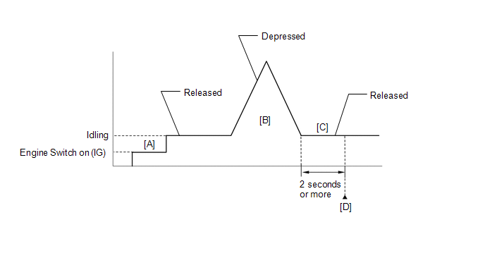
- Turn the engine switch on (IG) [A].
- Turn the Techstream on.
- Start the engine.
- With the vehicle stationary, fully depress and release the accelerator pedal [B].
- Idle the engine for 2 seconds or more [C].
- Enter the following menus: Powertrain / Engine / Trouble Codes [D].
-
Read the pending DTCs.
HINT:
- If a pending DTC is output, the system is malfunctioning.
- If a pending DTC is not output, perform the following procedure.
- Enter the following menus: Powertrain / Engine / Utility / All Readiness.
- Input the DTC: P012015.
-
Check the DTC judgment result.
Techstream Display
Description
NORMAL
- DTC judgment completed
- System normal
ABNORMAL
- DTC judgment completed
- System abnormal
INCOMPLETE
- DTC judgment not completed
- Perform driving pattern after confirming DTC enabling conditions
HINT:
- If the judgment result is NORMAL, the system is normal.
- If the judgment result is ABNORMAL, the system is malfunctioning.
- If the judgment result is INCOMPLETE, perform steps [B] through [D] again.
-
[A] to [D]: Normal judgment procedure.
The normal judgment procedure is used to complete DTC judgment and also used when clearing permanent DTCs.
- When clearing the permanent DTCs, do not disconnect the cable from the battery terminal or attempt to clear the DTCs during this procedure, as doing so will clear the universal trip and normal judgment histories.
FAIL-SAFE
When this DTC is stored, the ECM enters fail-safe mode. During fail-safe mode, the ECM cuts the current to the throttle actuator, and the throttle valve is returned to a 7° throttle valve opening angle by the return spring. The ECM then adjusts the engine output by controlling the fuel injection (intermittent fuel-cut) and ignition timing, in accordance with the accelerator pedal angle, to allow the vehicle to continue running at a minimal speed. If the accelerator pedal is depressed firmly and gently, the vehicle can be driven slowly.
Fail-safe mode continues until a pass condition is detected, and the engine switch is turned off.
WIRING DIAGRAM
Refer to DTC P012011.
Click here
CAUTION / NOTICE / HINT
HINT:
Read Freeze Frame Data using the Techstream. The ECM records vehicle and driving condition information as Freeze Frame Data the moment a DTC is stored. When troubleshooting, Freeze Frame Data can help determine if the vehicle was moving or stationary, if the engine was warmed up or not, if the air fuel ratio was lean or rich, and other data from the time the malfunction occurred.
PROCEDURE
| 1. | CHECK HARNESS AND CONNECTOR (THROTTLE POSITION SENSOR - ECM) |
(a) Disconnect the throttle body with motor assembly connector.
(b) Disconnect the ECM connector.
(c) Measure the resistance according to the value(s) in the table below.
Standard Resistance:
| Tester Connection | Condition | Specified Condition |
|---|---|---|
| C16-6 (VTA) - C32-122 (VTA1) | Always | Below 1 Ω |
| C16-3 (E2) - C32-120 (ETA) | Always | Below 1 Ω |
| C16-5 (VC) or C32-121 (VCTA) - Body ground and other terminals | Always | 10 kΩ or higher |
| C16-6 (VTA) or C32-122 (VTA1) - Body ground and other terminals | Always | 10 kΩ or higher |
| NG | .gif) | REPAIR OR REPLACE HARNESS OR CONNECTOR |
|
.gif)
| 2. | CHECK TERMINAL VOLTAGE (POWER SOURCE OF THROTTLE POSITION SENSOR) |
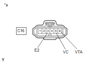
| *a | Front view of wire harness connector (to Throttle Body with Motor Assembly) |
(a) Disconnect the throttle body with motor assembly connector.
(b) Turn the engine switch on (IG).
(c) Measure the voltage according to the value(s) in the table below.
Standard Voltage:
| Tester Connection | Condition | Specified Condition |
|---|---|---|
| C16-5 (VC) - C16-3 (E2) | Engine switch on (IG) | 4.5 to 5.5 V |
| C16-6 (VTA) - C16-3 (E2) | Engine switch on (IG) | 3.0 to 5.0 V |
| NG | | REPLACE ECM |
|
| 3. | CHECK HARNESS AND CONNECTOR (RESISTANCE OF ECM) |
(a) Disconnect the throttle body with motor assembly connector.
(b) Measure the resistance according to the value(s) in the table below.
Standard Resistance:
| Tester Connection | Condition | Specified Condition |
|---|---|---|
| C16-5 (VC) - C16-6 (VTA) | Engine switch off | 190 to 210 kΩ |
| NG | | REPLACE ECM |
|
| 4. | READ VALUE USING TECHSTREAM (THROTTLE POSITION SENSOR NO.1 VOLTAGE) |
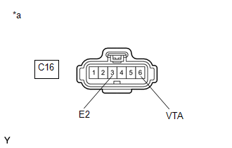
| *a | Front view of wire harness connector (to Throttle Body with Motor Assembly) |
(a) Disconnect the throttle body with motor assembly connector.
(b) Connect the Techstream to the DLC3.
(c) Turn the engine switch on (IG).
(d) Turn the Techstream on.
(e) Enter the following menus: Powertrain / Engine / Data List / Throttle Position Sensor No.1 Voltage.
Powertrain > Engine > Data List| Tester Display |
|---|
| Throttle Position Sensor No.1 Voltage |
(f) According to the display on the Techstream, read the Data List.
HINT:
Use the snapshot function to record the value displayed or make a note of it.
(g) Turn the engine switch off.
(h) Turn the Techstream off.
(i) Connect terminals 3 (E2) and 6 (VTA) of the throttle body with motor assembly connector on the wire harness side.
NOTICE:
If the VTA terminal voltage or the resistance between VTA and E2 is abnormal and terminals 6 (VTA) and 3 (E2) of the throttle body with motor assembly connector are connected, excessive current may flow through the circuit. In this case, do not connect the terminals.
(j) Turn the engine switch on (IG).
(k) Turn the Techstream on.
(l) Enter the following menus: Powertrain / Engine / Data List / Throttle Position Sensor No.1 Voltage.
Powertrain > Engine > Data List| Tester Display |
|---|
| Throttle Position Sensor No.1 Voltage |
(m) Compare the vehicle of the Data List item Throttle Position Sensor No.1 Voltage after the circuit is shorted to the value when the throttle body with motor assembly connector was connected.
| Result | Proceed to |
|---|---|
| Changes from higher than 4.535 V to less than 0.56 V | A |
| Does not change from higher than 4.535 V | B |
HINT:
Perform "Inspection After Repair" after replacing the throttle body with motor assembly.
Click here
| A | | REPLACE THROTTLE BODY WITH MOTOR ASSEMBLY |
| B | | REPLACE ECM |
READ NEXT:
 Throttle / Pedal Position Sensor / Switch "A" Circuit Voltage Out of Range (P01201C)
DESCRIPTION Refer to DTC P012011. Click here DTC No. Detection Item DTC Detection Condition Trouble Area MIL Memory Note P01201C Throttle / Pedal Position Sensor / Switch "A" Ci
Insufficient Coolant Temperature for Closed Loop Fuel Control (P012500)
DESCRIPTION Refer to DTC P011511. Click here DTC No. Detection Item DTC Detection Condition Trouble Area MIL Memory Note P012500 Insufficient Coolant Temperature for Closed Loop
Coolant Thermostat (Coolant Temperature Below Thermostat Regulating Temperature) (P012800,P012807)
DESCRIPTION The ECM uses the engine coolant temperature sensor, installed to the water outlet, to monitor the operation of the thermostat. DTC No. Detection Item DTC Detection Condition Troub
SEE MORE:
Terminals Of Ecu
TERMINALS OF ECU HYBRID VEHICLE CONTROL ECU Terminal No. (Symbol) Wiring Color Terminal Description Input/Output Condition Specified Condition A32-1 (+B2) - G59-6 (E1) W - W-B Power source Input Power switch on (IG) 11 to 14 V A32-3 (IG2) - G59-6 (E1) B - W-B Powe
Inspection
INSPECTION PROCEDURE 1. INSPECT OUTER MIRROR RH (a) Check the outer mirror heater operation. (1) Measure the resistance according to the value(s) in the table below. Standard Resistance: Tester Connection Condition Specified Condition 1 - 2 25°C (77°F) 3.8 to 5.8 Ω If the re
