Lexus ES: Removal
REMOVAL
CAUTION / NOTICE / HINT
The necessary procedures (adjustment, calibration, initialization or registration) that must be performed after parts are removed and installed, or replaced during air fuel ratio sensor removal/installation are shown below.
Necessary Procedures After Parts Removed/Installed/Replaced| Replaced Part or Performed Procedure | Necessary Procedure | Effect/Inoperative Function when Necessary Procedure not Performed | Link |
|---|---|---|---|
| Inspection after repair |
| |
PROCEDURE
1. REMOVE V-BANK COVER SUB-ASSEMBLY
Click here .gif)
2. REMOVE AIR FUEL RATIO SENSOR (for Bank 2)
| (a) Disengage the wire harness clamp. |
|
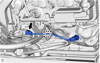
(b) Disconnect the air fuel ratio sensor connector.
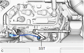
| (c) Using SST, remove the air fuel ratio sensor from the exhaust manifold assembly LH (TWC: Front Catalyst). SST: 09224-00012 NOTICE: If the air fuel ratio sensor has been struck or dropped, replace it. |
|
3. REMOVE AIR FUEL RATIO SENSOR (for Bank 1)
| (a) Disconnect the air fuel ratio sensor connector. |
|
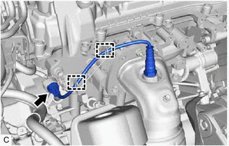
(b) Disengage the 2 wire harness clamps.
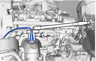
| (c) Using SST, remove the air fuel ratio sensor from the exhaust manifold assembly RH (TWC: Front Catalyst). SST: 09224-00012 NOTICE: If the air fuel ratio sensor has been struck or dropped, replace it. |
|
READ NEXT:
 Inspection
INSPECTION PROCEDURE 1. INSPECT AIR FUEL RATIO SENSOR (for Bank 1) (a) Measure the resistance according to the value(s) in the table below. Standard Resistance: Tester Connection Condition
Installation
INSTALLATION PROCEDURE 1. INSTALL AIR FUEL RATIO SENSOR (for Bank 1) HINT: Perform "Inspection After Repair" after replacing the air fuel ratio sensor. Click here (a) Using SST, install the air
SEE MORE:
Generator Inverter Actuator Stuck Closed (P0A7A73)
DTC SUMMARY MALFUNCTION DESCRIPTION This DTC is stored when a short is detected in the inverter with converter assembly (generator inverter) or the hybrid vehicle transaxle assembly (generator (MG1)). The cause of this malfunction may be one of the following: Internal inverter malfunction
Generat
Parts Location
PARTS LOCATION ILLUSTRATION *1 FUEL LID LOCK WITH MOTOR ASSEMBLY *2 FUEL LID OPENER SWITCH *3 INSTRUMENT PANEL JUNCTION BLOCK ASSEMBLY - FUEL OPN RELAY *4 NO. 1 ENGINE ROOM RELAY BLOCK AND NO. 1 JUNCTION BLOCK ASSEMBLY - FUEL OPN FUSE *5 TRUNK AND FUEL SWITCH ASSEMBLY -
