Lexus ES: Vehicle Approaching Speaker (for Front Side)
Components
COMPONENTS
ILLUSTRATION
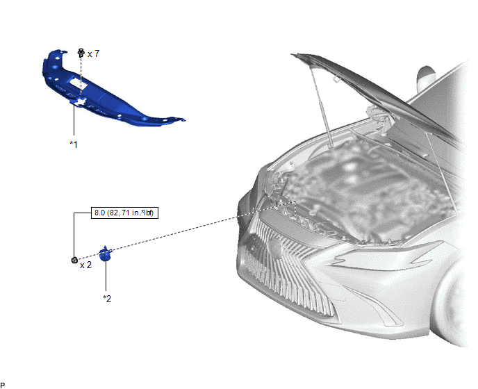
| *1 | COOL AIR INTAKE DUCT SEAL | *2 | VEHICLE APPROACHING SPEAKER ASSEMBLY |
.png) | N*m (kgf*cm, ft.*lbf): Specified torque | - | - |
Removal
REMOVAL
PROCEDURE
1. REMOVE COOL AIR INTAKE DUCT SEAL
Click here .gif)
2. REMOVE VEHICLE APPROACHING SPEAKER ASSEMBLY
| (a) Remove the 2 nuts. |
|
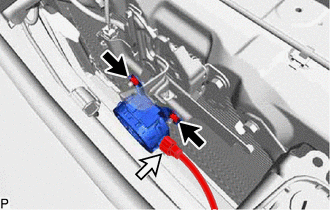
(b) Disconnect the connector to remove the vehicle approaching speaker assembly.
Inspection
INSPECTION
PROCEDURE
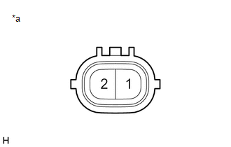
1. INSPECT VEHICLE APPROACHING SPEAKER ASSEMBLY
| (a) Measure the resistance according to the value(s) in the table below. Standard Resistance:
HINT: Make sure that the vehicle approaching speaker assembly is securely installed and not loose. If the result is not as specified, replace the vehicle approaching speaker assembly. |
|
Installation
INSTALLATION
PROCEDURE
1. INSTALL VEHICLE APPROACHING SPEAKER ASSEMBLY
(a) Connect the connector.
(b) Install the vehicle approaching speaker assembly with the 2 nuts.
Torque:
8.0 N·m {82 kgf·cm, 71 in·lbf}
2. INSTALL COOL AIR INTAKE DUCT SEAL
Click here .gif)
READ NEXT:
 Vehicle Approaching Speaker Ecu
ComponentsCOMPONENTS ILLUSTRATION *1 VEHICLE APPROACHING SPEAKER CONTROLLER - - N*m (kgf*cm, ft.*lbf): Specified torque - - RemovalREMOVAL PROCEDURE 1. REMOVE RADIO RECEIVER
Precaution
PRECAUTION PRECAUTION FOR DISCONNECTING CABLE FROM NEGATIVE AUXILIARY BATTERY TERMINAL NOTICE: When disconnecting the cable from the negative (-) auxiliary battery terminal, initialize the following s
SEE MORE:
Operation Check
OPERATION CHECK CHECK WINDSHIELD DEICER SYSTEM (a) Turn the power switch on (IG). (b) Check that the windshield deicer wire (windshield glass) becomes warm by operating the front wiper deicer switch. (c) Confirm that windshield deicer system operation stops after approximately 15 minutes. NOTICE: If
System Description
SYSTEM DESCRIPTION GRILLE SHUTTER SYSTEM (a) General description The swing grille actuator assembly receives signals from the ECM, hybrid vehicle control ECU and air conditioning amplifier assembly via CAN communication. Based on these signals, the swing grille actuator assembly operates the radiato
