Lexus ES: Installation
INSTALLATION
PROCEDURE
1. INSTALL AIR FUEL RATIO SENSOR (for Bank 1)
HINT:
Perform "Inspection After Repair" after replacing the air fuel ratio sensor.
Click here .gif)
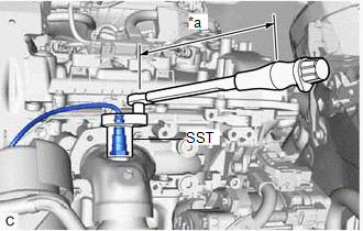
| (a) Using SST, install the air fuel ratio sensor to the exhaust manifold assembly RH (TWC: Front Catalyst). SST: 09224-00012 Torque: Specified tightening torque : 44 N·m {449 kgf·cm, 32 ft·lbf} NOTICE: If the air fuel ratio sensor has been struck or dropped, replace it. HINT:
|
|
(b) Engage the 2 wire harness clamps.
(c) Connect the air fuel ratio sensor connector.
2. INSTALL AIR FUEL RATIO SENSOR (for Bank 2)
HINT:
Perform "Inspection After Repair" after replacing the air fuel ratio sensor.
Click here
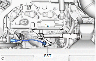
| (a) Using SST, install the air fuel ratio sensor to the exhaust manifold assembly LH (TWC: Front Catalyst). SST: 09224-00012 Torque: Specified tightening torque : 44 N·m {449 kgf·cm, 32 ft·lbf} NOTICE: If the air fuel ratio sensor has been struck or dropped, replace it. HINT:
|
|
(b) Connect the air fuel ratio sensor connector.
(c) Engage the wire harness clamp.
3. INSTALL V-BANK COVER SUB-ASSEMBLY
Click here
4. INSPECT FOR EXHAUST GAS LEAK
Click here
5. PERFORM INITIALIZATION
(a) Perform "Inspection After Repair" after replacing an air fuel ratio sensor.
Click here
READ NEXT:
 Components
COMPONENTS ILLUSTRATION *1 FRONT FENDER APRON SEAL RH *2 V-BANK COVER SUB-ASSEMBLY N*m (kgf*cm, ft.*lbf): Specified torque - - ILLUSTRATION *1 CAMSHAFT TIMING OIL CONTROL
On-vehicle Inspection
ON-VEHICLE INSPECTION PROCEDURE 1. INSPECT CAMSHAFT TIMING OIL CONTROL SOLENOID ASSEMBLY (a) Connect the Techstream to the DLC3. (b) Start the engine. (c) Turn the Techstream on. (d) Inspect the camsh
SEE MORE:
Removal
REMOVAL CAUTION / NOTICE / HINT The necessary procedures (adjustment, calibration, initialization or registration) that must be performed after parts are removed and installed, or replaced during fuel pump control ECU removal/installation are shown below. Necessary Procedures After Parts Removed/Ins
Removal
REMOVAL CAUTION / NOTICE / HINT The necessary procedures (adjustment, calibration, initialization, or registration) that must be performed after parts are replaced during millimeter wave radar sensor assembly removal/installation are shown below. Necessary Procedure After Parts Removed/Installed/Rep
