Lexus ES: Removal
REMOVAL
CAUTION / NOTICE / HINT
The necessary procedures (adjustment, calibration, initialization, or registration) that must be performed after parts are removed and installed, or replaced during rear brake flexible hose removal/installation are shown below.
Necessary Procedures After Parts Removed/Installed/Replaced (for HV Model)|
Replaced Part or Performed Procedure |
Necessary Procedure |
Effect/Inoperative Function when Necessary Procedure not Performed |
Link |
|---|---|---|---|
| *: When performing learning using the Techstream.
Click here |
|||
|
Auxiliary battery terminal is disconnected/reconnected |
Perform steering sensor zero point calibration |
Lane Control System (for HV Model) |
|
|
Pre-collision System (for HV Model) |
|||
|
Parking Support Brake System (for HV Model)* |
|||
|
Lighting System (for HV Model) |
|||
|
Memorize steering angle neutral point |
Parking Assist Monitor System (for HV Model) |
|
|
|
Panoramic View Monitor System (for HV Model) |
|
||
|
Initialize power trunk lid system |
Power Trunk Lid System (for HV Model) |
|
|
NOTICE:
- If both left and right rear flexible hoses are disconnected at the same time, be sure to place an identification mark on each hose to indicate its installation position.
- After the power switch is turned off, the radio receiver assembly records various types of memory and settings. As a result, after turning the power switch off, make sure to wait at least 85 seconds before disconnecting the cable from the negative (-) auxiliary battery terminal. (for Audio and Visual System)
- After the power switch is turned off, the radio receiver assembly records various types of memory and settings. As a result, after turning the power switch off, make sure to wait at least 85 seconds before disconnecting the cable from the negative (-) auxiliary battery terminal. (for Navigation System)
HINT:
- Use the same procedure for the RH side and LH side.
- The following procedure is for the LH side.
PROCEDURE
1. PRECAUTION (for HV Model)
NOTICE:
After turning the power switch off, waiting time may be required before disconnecting the cable from the negative (-) auxiliary battery terminal. Therefore, make sure to read the disconnecting the cable from the negative (-) auxiliary battery terminal notices before proceeding with work.
2. DISABLE BRAKE CONTROL (for HV Model)
Click here .gif)
3. REMOVE REAR WHEEL
Click here
4. DRAIN BRAKE FLUID
NOTICE:
If brake fluid leaks onto any painted surface, immediately wash it off.
5. REMOVE REAR FLEXIBLE HOSE
|
(a) Remove the union bolt and gasket, and disconnect the rear flexible hose from the rear disc brake cylinder assembly. |
|
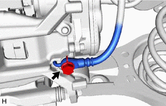
|
(b) Remove the bolt and separate the rear flexible hose from the rear flexible hose bracket. |
|
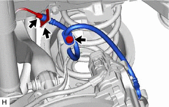
(c) Using a union nut wrench, disconnect the brake line while holding the rear flexible hose with a wrench.
NOTICE:
- Do not kink or damage the brake line.
- Do not allow any foreign matter such as dirt or dust to enter the brake line from the connecting parts.
(d) Remove the clip and rear flexible hose from the vehicle body.
READ NEXT:
 Installation
INSTALLATION
CAUTION / NOTICE / HINT
NOTICE:
Because the left and right rear flexible hoses are not interchangeable,
verify the part number when installing the rear flexible hoses.
Components
COMPONENTS
ILLUSTRATION
*1
NO. 2 PARKING BRAKE WIRE ASSEMBLY
*2
REAR DISC BRAKE ANTI-SQUEAL SHIM KIT
*3
REAR DISC BRAKE PAD
SEE MORE:
Vehicle Identification Malfunction (C1789)
DESCRIPTION When the absorber control ECU has not acquired the vehicle identification information, DTC C1789 is stored. When the vehicle identification information is correctly acquired, this DTC is cleared. Vehicle identification information is automatically acquired when the system enters test mod
Components
COMPONENTS ILLUSTRATION *1 FRONT CENTER UPPER SUSPENSION BRACE SUB-ASSEMBLY - - Tightening torque for "Major areas involving basic vehicle performance such as moving/turning/stopping": N*m (kgf*cm, ft.*lbf) N*m (kgf*cm, ft.*lbf): Specified torque *T1 Bolt color black: 8.0
