Lexus ES: Parts Location
PARTS LOCATION
ILLUSTRATION
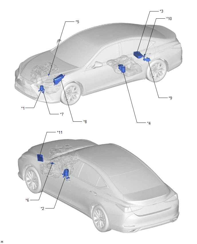
| *1 | FRONT ENGINE MOUNTING INSULATOR | *2 | REAR ENGINE MOUNTING INSULATOR |
| *3 | CANISTER | *4 | FUEL PUMP (for Low Pressure Side) |
| *5 | MASS AIR FLOW METER SUB-ASSEMBLY | *6 | PARK / NEUTRAL POSITION SWITCH ASSEMBLY |
| *7 | VACUUM SWITCHING VALVE (for Active Control Engine Mount System) | *8 | NO. 1 ENGINE ROOM RELAY BLOCK AND NO. 1 JUNCTION BLOCK ASSEMBLY |
| *9 | CANISTER PUMP MODULE | *10 | FUEL PUMP CONTROL ECU |
| *11 | ECM | - | - |
ILLUSTRATION
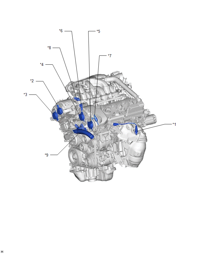
| *1 | AIR FUEL RATIO SENSOR (Bank 2 Sensor 1) | *2 | CAM TIMING OIL CONTROL SOLENOID ASSEMBLY (for Intake Camshaft of Bank 1) |
| *3 | CAM TIMING OIL CONTROL SOLENOID ASSEMBLY (for Exhaust Camshaft of Bank 1) | *4 | CAM TIMING OIL CONTROL SOLENOID ASSEMBLY (for Intake Camshaft of Bank 2) |
| *5 | CAM TIMING OIL CONTROL SOLENOID ASSEMBLY (for Exhaust Camshaft of Bank 2) | *6 | PORT FUEL INJECTOR ASSEMBLY |
| *7 | DIRECT FUEL INJECTOR ASSEMBLY | *8 | FUEL PRESSURE SENSOR (for Low Pressure Side) |
| *9 | WATER INLET WITH THERMOSTAT SUB-ASSEMBLY | - | - |
ILLUSTRATION
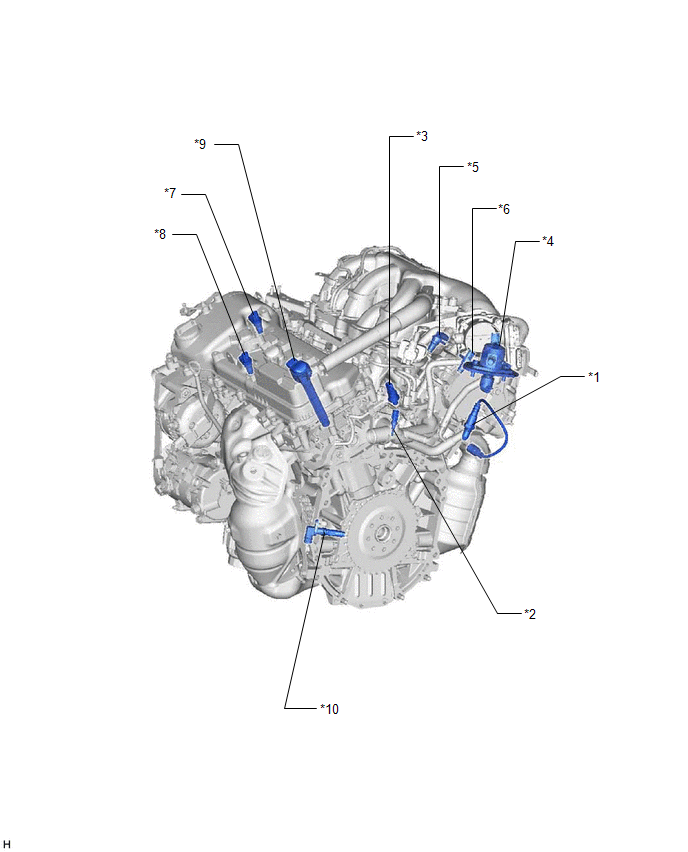
| *1 | AIR FUEL RATIO SENSOR (Bank 1 Sensor 1) | *2 | ENGINE COOLANT TEMPERATURE SENSOR |
| *3 | FUEL PRESSURE SENSOR (for High Pressure Side) | *4 | FUEL PUMP ASSEMBLY (for High Pressure Side) |
| *5 | VVT SENSOR (for Intake Camshaft of Bank 1) | *6 | VVT SENSOR (for Exhaust Camshaft of Bank 1) |
| *7 | VVT SENSOR (for Intake Camshaft of Bank 2) | *8 | VVT SENSOR (for Exhaust Camshaft of Bank 2) |
| *9 | IGNITION COIL ASSEMBLY | *10 | CRANKSHAFT POSITION SENSOR |
ILLUSTRATION
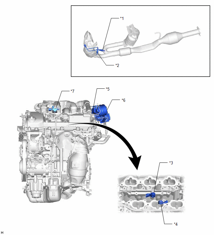
| *1 | HEATED OXYGEN SENSOR (Bank 1 Sensor 2) | *2 | HEATED OXYGEN SENSOR (Bank 2 Sensor 2) |
| *3 | KNOCK CONTROL SENSOR (Bank 1) | *4 | KNOCK CONTROL SENSOR (Bank 2) |
| *5 | PURGE VSV | *6 | THROTTLE BODY WITH MOTOR ASSEMBLY |
| *7 | NO. 1 VACUUM SWITCHING VALVE (for Intake Air Control Valve Sub-assembly) | - | - |
ILLUSTRATION
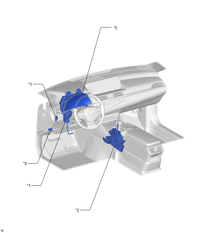
| *1 | ACCELERATOR PEDAL SENSOR ASSEMBLY | *2 | TRANSMISSION CONTROL SWITCH (SHIFT LOCK CONTROL UNIT ASSEMBLY) |
| *3 | STOP LIGHT SWITCH ASSEMBLY | *4 | DLC3 |
| *5 | COMBINATION METER ASSEMBLY | - | - |
READ NEXT:
 System Diagram
SYSTEM DIAGRAM
How To Proceed With Troubleshooting
CAUTION / NOTICE / HINT HINT: *: Use the Techstream. PROCEDURE 1. VEHICLE BROUGHT TO WORKSHOP
NEXT 2. CUSTOMER PROBLEM ANALYSIS
NEXT 3. CONNEC
Check For Intermittent Problems
CHECK FOR INTERMITTENT PROBLEMS HINT: Inspect the vehicle ECM using check mode. Intermittent problems are easier to detect with the Techstream when the ECM is in check mode. In check mode, the ECM use
SEE MORE:
Components
COMPONENTS ILLUSTRATION *1 FRONT DOOR FRONT LOWER FRAME UPPER COVER *2 FRONT DOOR GLASS RUN *3 FRONT DOOR OUTSIDE MOULDING SUB-ASSEMBLY *4 FRONT DOOR REAR WINDOW FRAME MOULDING *5 FRONT DOOR WEATHERSTRIP *6 RIVET ● Non-reusable part - -
Rear Height Control Sensor (B241A)
DESCRIPTION The headlight ECU sub-assembly LH determines the vehicle height and performs automatic headlight beam level control based on signals from the rear height control sensor sub-assembly LH via direct line. DTC No. Detection Item DTC Detection Condition Trouble Area DTC Output from
