Lexus ES: Reassembly
REASSEMBLY
PROCEDURE
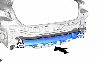
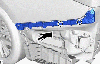
1. INSTALL REAR BUMPER REINFORCEMENT
| (a) Install the rear bumper reinforcement with the 6 bolts. Torque: 35 N·m {357 kgf·cm, 26 ft·lbf} |
|
.png)
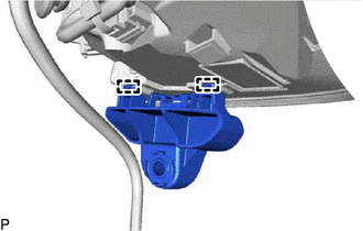
2. INSTALL REAR BUMPER PROTECTOR INSERT LH
| (a) Engage the guide and claw to install the rear bumper protector insert LH. |
|
.png)
3. INSTALL REAR BUMPER PROTECTOR INSERT RH
HINT:
Use the same procedure as for the LH side.
4. INSTALL REAR BUMPER PROTECTOR LH
(a) Temporarily install the rear bumper protector LH as shown in the illustration.
.png) | Install in this Direction |
(b) Install the rear bumper protector LH with the screw.
5. INSTALL REAR BUMPER PROTECTOR RH
HINT:
Use the same procedure as for the LH side.
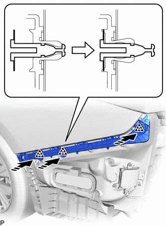
6. INSTALL REAR BUMPER ENERGY ABSORBER
(a) Engage the 2 guides to install the rear bumper energy absorber as shown in the illustration.
| | Install in this Direction |
7. INSTALL REAR BUMPER SIDE SUPPORT RH
| (a) Install the 3 clips. |
|
.png)
| (b) Install the rear bumper side support RH with 2 new grommets. |
|
.png)
8. INSTALL REAR BUMPER SIDE SUPPORT LH
| (a) Install the 2 clips. |
|
.png)
| (b) Install the rear bumper side support LH with 2 new grommets. |
|
.png)
9. INSTALL LOWER REAR BUMPER SIDE RETAINER LH
| (a) Engage the 2 clips. |
|
.png)
(b) Install the lower rear bumper side retainer LH with the screw.
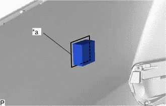
10. INSTALL REAR BUMPER UPPER RETAINER LH
(a) Engage the grommet.
| (b) Engage the 2 guides to temporarily install the rear bumper upper retainer LH to the rear combination light lens and body LH. |
|
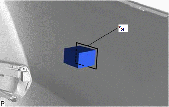
(c) Engage the guide and pin as shown in the illustration to temporarily install the rear bumper upper retainer LH and rear combination light lens and body LH as a set.
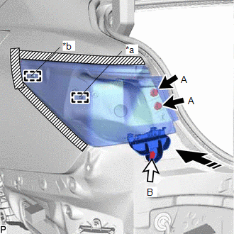
| *a | Pin |
| *b | Guide |
| | Install in this Direction |
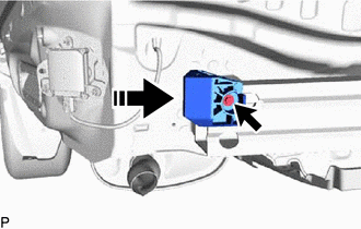
(d) Install the rear combination light assembly LH with the 2 screws (A).
(e) Connect the connector.
(f) Install the rear bumper upper retainer LH with the screw (B).
11. INSTALL REAR BUMPER UPPER RETAINER RH
HINT:
Use the same procedure as for the LH side.
12. INSTALL LUGGAGE COMPARTMENT TRIM INNER COVER LH
Click here .gif)
13. INSTALL LUGGAGE COMPARTMENT TRIM INNER COVER RH
Click here
14. INSTALL LUGGAGE COMPARTMENT TRIM COVER LH
Click here
15. INSTALL LUGGAGE COMPARTMENT TRIM COVER RH
Click here
16. INSTALL REAR FLOOR FINISH PLATE
Click here
17. INSTALL SPARE WHEEL COVER TRAY
Click here
18. INSTALL LUGGAGE COMPARTMENT FLOOR MAT
Click here
19. INSTALL NO. 2 REAR BUMPER SIDE SUPPORT LH
(a) Engage the 2 claws as shown in the illustration.
| | Install in this Direction |
(b) Engage the 3 clips as shown in the illustration to install the No. 2 rear bumper side support LH.
| | Install in this Direction |
20. INSTALL NO. 2 REAR BUMPER SIDE SUPPORT RH
HINT:
Use the same procedure as for the LH side.
21. INSTALL REAR BUMPER BAR LH
| (a) Engage the guide and 2 claws. |
|
.png)
| (b) Install the rear bumper bar LH with the screw. |
|
.png)
22. INSTALL REAR BUMPER BAR RH
HINT:
Use the same procedure as for the LH side.
23. INSTALL REAR BUMPER BAR
| (a) Engage the 2 guides and 4 claws. |
|
.png)
| (b) Install the rear bumper bar with the 3 screws. |
|
.png)
24. INSTALL REAR CENTER BUMPER SUB-ASSEMBLY
25. INSTALL REFLEX REFLECTOR ASSEMBLY
| (a) Engage the guide and claw. HINT: Use the same procedure for the RH side and LH side. |
|
.png)
(b) Install the reflex reflector assembly with the screw.
HINT:
Use the same procedure for the RH side and LH side.
(c) Engage the 14 claws.
.png)
| (d) Install the 2 screws. |
|
.png)
26. INSTALL REAR BUMPER PAD RH
HINT:
When installing the rear bumper pad RH, heat the rear bumper cover using a heat light.
Heating Temperature| Item | Temperature |
|---|---|
| Rear Bumper Cover | 20 to 30°C (68 to 86°F) |
CAUTION:
- Do not touch the heat light and heated parts, touching the heat light may result in burns.
- Touching heated parts for a long time may result in burns.
.png)
| *a | Heated Part |
| *b | Heat Light |
NOTICE:
Do not heat the rear bumper cover excessively.
(a) Clean the rear bumper cover surface.
(1) Using a heat light, heat the rear bumper cover surface.
(2) Remove any remaining double-sided tape from the rear bumper cover.
(3) Wipe off any tape adhesive residue with cleaner.
(b) Remove the release paper from a new rear bumper pad RH.
HINT:
After removing the release paper, keep the exposed adhesive free from foreign matter.
| (c) Install the rear bumper pad RH as shown in the illustration. HINT: Press the rear bumper pad RH firmly to install it. |
|
27. INSTALL REAR BUMPER PAD LH
HINT:
When installing the rear bumper pad LH, heat the rear bumper cover using a heat light.
Heating Temperature| Item | Temperature |
|---|---|
| Rear Bumper Cover | 20 to 30°C (68 to 86°F) |
CAUTION:
- Do not touch the heat light and heated parts, touching the heat light may result in burns.
- Touching heated parts for a long time may result in burns.
| *a | Heated Part |
| *b | Heat Light |
NOTICE:
Do not heat the rear bumper cover excessively.
(a) Clean the rear bumper cover surface.
(1) Using a heat light, heat the rear bumper cover surface.
(2) Remove any remaining double-sided tape from the rear bumper cover.
(3) Wipe off any tape adhesive residue with cleaner.
(b) Remove the release paper from a new rear bumper pad LH.
HINT:
After removing the release paper, keep the exposed adhesive free from foreign matter.
| (c) Install the rear bumper pad LH as shown in the illustration. HINT: Press the rear bumper pad LH firmly to install it. |
|
28. INSTALL NO. 1 MOULDING TAPE
HINT:
- Use the same procedure for the LH side and RH side.
- When installing the No. 1 moulding tape, heat the rear bumper cover using a heat light.
| Item | Temperature |
|---|---|
| Rear Bumper Cover | 20 to 30°C (68 to 86°F) |
CAUTION:
- Do not touch the heat light and heated parts, touching the heat light may result in burns.
- Touching heated parts for a long time may result in burns.
| *a | Heated Part |
| *b | Heat Light |
NOTICE:
Do not heat the rear bumper cover excessively.
(a) Clean the rear bumper cover surface.
(1) Using a heat light, heat the rear bumper cover surface.
(2) Remove any remaining double-sided tape from the rear bumper cover.
(3) Wipe off any tape adhesive residue with cleaner.
(b) Remove the release paper from a new No. 1 moulding tape.
HINT:
After removing the release paper, keep the exposed adhesive free from foreign matter.
| (c) Install the No. 1 moulding tape as shown in the illustration. HINT: Press the No. 1 moulding tape firmly to install it. |
|
29. INSTALL ULTRASONIC SENSOR CLIP (w/ Wire Harness)
HINT:
When installing the ultrasonic sensor clip, heat the rear bumper cover using a heat light.
Heating Temperature| Item | Temperature |
|---|---|
| Rear Bumper Cover | 20 to 30°C (68 to 86°F) |
CAUTION:
- Do not touch the heat light and heated parts, touching the heat light may result in burns.
- Touching heated parts for a long time may result in burns.
| *a | Heated Part |
| *b | Heat Light |
NOTICE:
Do not heat the rear bumper cover excessively.
(a) Clean the rear bumper cover surface.
(1) Using a heat light, heat the rear bumper cover surface.
(2) Remove any remaining double-sided tape from the rear bumper cover.
(3) Wipe off any tape adhesive residue with cleaner.
(b) Using a brush or felt, apply primer or equivalent to the ultrasonic sensor clip installation area.
.png)
.png) | Primer |
NOTICE:
- Use a clean brush or felt.
- Do not touch the rear bumper cover until the primer has dried.
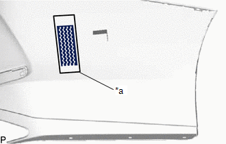
(c) w/ Hands Free Power Trunk Lid without Parking Support Alert System:
(1) Remove the release paper from a new ultrasonic sensor clip.
HINT:
After removing the release paper, keep the exposed adhesive free from foreign matter.
(2) Install the ultrasonic sensor clip as shown in the illustration.
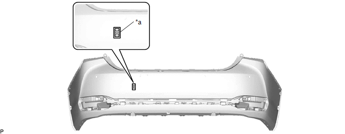
| *a | Line | - | - |
HINT:
Press the ultrasonic sensor clip firmly to install it.
(d) w/ Parking Support Alert System without Hands Free Power Trunk Lid:
(1) Remove the release paper from 3 new ultrasonic sensor clips.
HINT:
After removing the release paper, keep the exposed adhesive free from foreign matter.
(2) Install the 3 ultrasonic sensor clips as shown in the illustration.
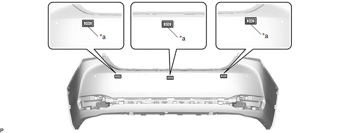
| *a | Line | - | - |
HINT:
Press the ultrasonic sensor clip firmly to install it.
(e) w/ Hands Free Power Trunk Lid and Parking Support Alert System:
(1) Remove the release paper from 4 new ultrasonic sensor clips.
HINT:
After removing the release paper, keep the exposed adhesive free from foreign matter.
(2) Install the 4 ultrasonic sensor clips as shown in the illustration.
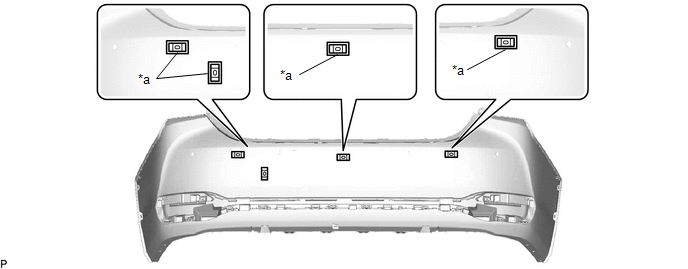
| *a | Line | - | - |
HINT:
Press the ultrasonic sensor clip firmly to install it.
30. INSTALL NO. 2 LUGGAGE ROOM WIRE (w/ Wire Harness)
(a) w/ Hands Free Power Trunk Lid without Parking Support Alert System:
(1) Engage the clamp to install the No. 2 luggage room wire.
.png)
(b) w/ Parking Support Alert System without Hands Free Power Trunk Lid:
(1) Engage the 3 clamps to install the No. 2 luggage room wire.
.png)
(c) w/ Hands Free Power Trunk Lid and Parking Support Alert System:
(1) Engage the 4 clamps to install the No. 2 luggage room wire.
.png)
31. INSTALL REAR CORNER ULTRASONIC SENSOR RETAINER (w/ Parking Support Alert System)
Click here
HINT:
Use the same procedure for the RH side and LH side.
32. INSTALL REAR CENTER ULTRASONIC SENSOR RETAINER (w/ Parking Support Alert System)
Click here
HINT:
Use the same procedure for the RH side and LH side.
33. INSTALL REAR CORNER ULTRASONIC SENSOR (w/ Parking Support Alert System)
Click here
HINT:
Use the same procedure for the RH side and LH side.
34. INSTALL REAR CENTER ULTRASONIC SENSOR (w/ Parking Support Alert System)
Click here
HINT:
Use the same procedure for the RH side and LH side.
35. INSTALL KICK DOOR CONTROL SENSOR WITH BRACKET (w/ Hands Free Power Trunk Lid)
Click here
READ NEXT:
 Installation
INSTALLATION PROCEDURE 1. INSTALL REAR BUMPER ASSEMBLY (a) w/ Wire Harness: (1) Connect the connector. (b) Engage the 6 claws as shown in the illustration. Install in this Direction (c) Enga
Components
COMPONENTS ILLUSTRATION *1 COURTESY LIGHT ASSEMBLY *2 REAR DOOR TRIM BOARD SUB-ASSEMBLY *3 REAR DOOR UPPER TRIM PAD *4 REAR POWER WINDOW REGULATOR SWITCH ASSEMBLY WITH REAR DOOR UP
SEE MORE:
Installation
INSTALLATION PROCEDURE 1. INSTALL CLEARANCE WARNING ECU ASSEMBLY (a) Engage the claw to install the clearance warning ECU assembly as shown in the illustration. Install in this Direction 2. INSTALL ECU INTEGRATION BOX RH Click here 3. INSTALL GLOVE COMPARTMENT DOOR ASSEMBLY Click here
Exhaust Gas Recirculation "A" Flow (P040000-P04029B)
DESCRIPTION Based on the driving conditions, the ECM regulates the volume of exhaust gas that is recirculated to each engine cylinder in order to lower the combustion temperature and reduce NOx emissions. The ECM monitors signals such as engine speed, engine coolant temperature, electric load, and v
