Lexus ES: Disassembly
DISASSEMBLY
CAUTION / NOTICE / HINT
HINT:
- Use the same procedure for the RH side and LH side.
- The following procedure is for the LH side.
PROCEDURE
1. SEPARATE FRONT NO. 2 AXLE INBOARD JOINT BOOT CLAMP
(a) for TMC Made:
(1) Secure the drive shaft in a vise between aluminum plates.
NOTICE:
Do not overtighten the vise.
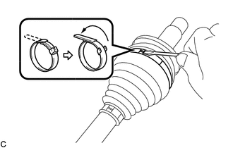
| (2) Using a screwdriver, separate the front No. 2 axle inboard joint boot clamp as shown in the illustration. |
|
(b) for TMMK Made:
(1) Secure the drive shaft in a vise between aluminum plates.
NOTICE:
Do not overtighten the vise.
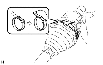
| (2) Using pliers, separate the front No. 2 axle inboard joint boot clamp as shown in the illustration. |
|
.png)
2. SEPARATE FRONT AXLE INBOARD JOINT BOOT CLAMP
HINT:
Perform the same procedure as for the front No. 2 axle inboard joint boot clamp.
3. SEPARATE FRONT AXLE INBOARD JOINT BOOT
(a) Separate the front axle inboard joint boot from the front drive inboard joint assembly.
4. REMOVE FRONT DRIVE INBOARD JOINT ASSEMBLY
(a) Remove the old grease from the front drive inboard joint assembly.
| (b) Put matchmarks on the front drive inboard joint assembly and front drive outboard joint shaft assembly. NOTICE: Do not use a punch for the marks. |
|
.png)
(c) Remove the front drive inboard joint assembly from the front drive outboard joint shaft assembly.
(d) Secure the drive shaft in a vise between aluminum plates.
NOTICE:
Do not overtighten the vise.
| (e) Using a snap ring expander, remove the shaft snap ring from the front drive outboard joint shaft assembly. |
|
.png)
| (f) Put matchmarks on the front drive outboard joint shaft assembly and tripod joint. NOTICE: Do not use a punch for the marks. |
|
.png)
(g) Using a brass bar and a hammer, tap out the tripod joint from the front drive outboard joint shaft assembly.
NOTICE:
- Do not tap the rollers.
- Do not drop the tripod joint.
(h) for TMMK Made:
| (1) Remove the front axle inboard joint grommet from the front drive inboard joint assembly. |
|
.png)
5. REMOVE FRONT AXLE INBOARD JOINT BOOT
(a) Remove the front No. 2 axle inboard joint boot clamp, front axle inboard joint boot and front axle inboard joint boot clamp.
6. REMOVE FRONT DRIVE SHAFT DAMPER CLAMP
(a) Secure the drive shaft in a vise between aluminum plates.
NOTICE:
Do not overtighten the vise.
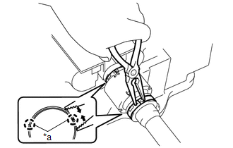
| (b) Using needle-nose pliers, disengage each claw as shown in the illustration and separate the 2 front drive shaft damper clamps. |
|
7. REMOVE FRONT DRIVE SHAFT DAMPER
(a) Remove the front drive shaft damper and 2 front drive shaft damper clamps from the front drive outboard joint shaft assembly.
8. SEPARATE FRONT NO. 2 AXLE OUTBOARD JOINT BOOT CLAMP
(a) Secure the drive shaft in a vise between aluminum plates.
NOTICE:
Do not overtighten the vise.
(b) for TMC Made:
| (1) Using a screwdriver, separate the front No. 2 axle outboard joint boot clamp. |
|
(c) for TMMK Made:
| (1) Using pliers, separate the front No. 2 axle outboard joint boot clamp. |
|
.png)
9. SEPARATE FRONT AXLE OUTBOARD JOINT BOOT CLAMP
HINT:
Perform the same procedure as for the front No. 2 axle outboard joint boot clamp.
10. REMOVE FRONT AXLE OUTBOARD JOINT BOOT
(a) Remove the front axle outboard joint boot clamp, front axle outboard joint boot and front No. 2 axle outboard joint boot clamp from the front drive outboard joint shaft assembly.
(b) Remove the old grease from the outboard joint.
READ NEXT:
 Inspection
INSPECTION PROCEDURE 1. INSPECT FRONT DRIVE SHAFT ASSEMBLY (a) Check that there is no excessive play in the radial direction of the outboard joint. (b) Check that the inboard joint slid
Installation
INSTALLATION CAUTION / NOTICE / HINT HINT:
Use the same procedure for the RH side and LH side.
The following procedure is for the LH side.
PROCEDURE 1. INSTALL FRONT DRIVE SHAFT HOLE SNAP RING
Reassembly
REASSEMBLY CAUTION / NOTICE / HINT HINT:
Use the same procedure for the RH side and LH side.
The following procedure is for the LH side.
PROCEDURE 1. INSTALL FRONT AXLE OUTBOARD JOINT BOOT (a)
SEE MORE:
Components
COMPONENTS ILLUSTRATION *A for EGR Valve Bracket Connection Type - - *1 NO. 1 EGR PIPE SUB-ASSEMBLY *2 EGR VALVE ASSEMBLY *3 EGR VALVE BRACKET *4 EGR INLET GASKET *5 EGR VALVE ADAPTER GASKET *6 EGR VALVE GASKET *7 NO. 8 WATER BY-PASS HOSE *8 NO. 4 WA
Control Module Communication Bus Off (U0073,U0100,U0101,U0126,U0129,U0142,U0155,U0242)
DESCRIPTION These DTCs are stored if a CAN communication malfunction occurs between the headlight ECU sub-assembly LH and other ECUs. for LED Type Turn Signal Light DTC No. Detection Item DTC Detection Condition Trouble Area DTC Output from U0073 Control Module Communication Bus Off
