Lexus ES: Removal
REMOVAL
CAUTION / NOTICE / HINT
The necessary procedures (adjustment, calibration, initialization, or registration) that must be performed after parts are removed and installed, or replaced during rear axle carrier sub-assembly removal/installation are shown below.
Necessary Procedures After Parts Removed/Installed/Replaced| Replaced Part or Performed Procedure | Necessary Procedure | Effect/Inoperative Function when Necessary Procedure not Performed | Link |
|---|---|---|---|
| *1: for LED Type Turn Signal Light | |||
| Suspension, tires, etc. (The vehicle height changes because of suspension or tire replacement.) |
|
| |
| Rear television camera assembly optical axis adjustment (Back camera position setting) | Parking Assist Monitor System | | |
| Panoramic View Monitor System | | |
| Perform headlight ECU sub-assembly LH initialization*1 | Lighting System | | |
| Rear height control sensor sub-assembly LH | Perform headlight ECU sub-assembly LH initialization*1 | Lighting System | |
| Rear wheel alignment adjustment |
|
| |
CAUTION / NOTICE / HINT
HINT:
- Use the same procedure for the RH side and LH side.
- The following procedure is for the LH side.
PROCEDURE
1. REMOVE REAR WHEEL
Click here .gif)
2. REMOVE REAR AXLE SHAFT NUT
Click here
3. SEPARATE NO. 2 PARKING BRAKE WIRE ASSEMBLY
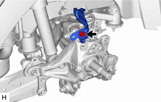
| (a) Disconnect the No. 2 parking brake wire assembly connector from the parking brake actuator assembly. NOTICE:
|
|
.png)
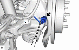
| (b) Using a screwdriver with its tip wrapped with protective tape, disconnect the No. 2 parking brake wire assembly connector from the rear skid control sensor. NOTICE:
|
|
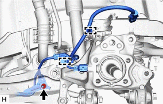
| (c) Remove the nut, disengage the 2 clamps and separate the No. 2 parking brake wire assembly from the rear flexible hose bracket and rear trailing arm assembly. |
|
4. REMOVE REAR SKID CONTROL SENSOR
Click here
5. SEPARATE REAR FLEXIBLE HOSE
| (a) Remove the bolt and separate the rear flexible hose from the rear flexible hose bracket. |
|
.png)
6. SEPARATE REAR DISC BRAKE CALIPER ASSEMBLY
Click here
7. REMOVE REAR DISC
Click here
8. REMOVE REAR AXLE HUB AND BEARING ASSEMBLY
Click here
9. REMOVE REAR FLEXIBLE HOSE BRACKET
| (a) Remove the bolt and rear flexible hose bracket from the rear axle carrier sub-assembly. |
|
10. REMOVE REAR HEIGHT CONTROL SENSOR SUB-ASSEMBLY LH (w/ Height Control Sensor)
(a) for LH Side:
Click here
11. REMOVE REAR STABILIZER LINK ASSEMBLY
Click here
12. REMOVE REAR COIL SPRING
Click here
13. REMOVE REAR LOWER COIL SPRING INSULATOR
Click here
14. REMOVE REAR NO. 1 SUSPENSION ARM ASSEMBLY
Click here
15. REMOVE REAR AXLE CARRIER SUB-ASSEMBLY
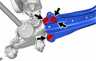
| (a) Loosen the 3 bolts and nut of the rear trailing arm assembly. |
|
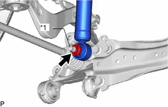
| (b) Loosen the nut of the rear shock absorber assembly. NOTICE: Hold the rear axle carrier pin while rotating the nut. |
|
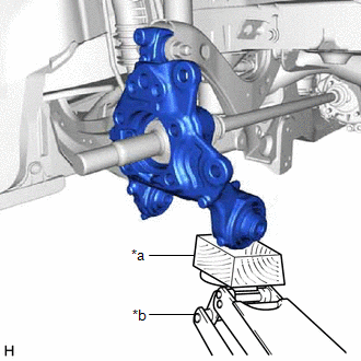
| (c) Using a jack and a wooden block, support the rear axle carrier sub-assembly. NOTICE:
|
|
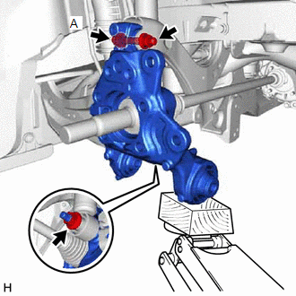
| (d) Loosen the bolt (A). NOTICE: Because the nut has its own stopper, do not turn the nut. Loosen the bolt with the nut secured. |
|
(e) Remove the 3 bolts, nut and separate the rear trailing arm assembly from the rear axle carrier sub-assembly.
(f) Remove the nut and plate washer, and separate the rear shock absorber assembly from the rear axle carrier sub-assembly.
NOTICE:
Hold the rear axle carrier pin while rotating the nut.
(g) Remove the bolt (A), nut and rear axle carrier sub-assembly from the rear upper control arm assembly.
NOTICE:
- Because the nut has its own stopper, do not turn the nut. Loosen the bolt with the nut secured.
- Use wire or an equivalent tool to keep the rear drive shaft assembly from hanging down.
READ NEXT:
 Components
COMPONENTS ILLUSTRATION *1 NO. 2 PARKING BRAKE WIRE ASSEMBLY *2 REAR AXLE HUB AND BEARING ASSEMBLY *3 REAR DISC *4 REAR DISC BRAKE CALIPER ASSEMBLY *5 REAR FLEXIBLE HOSE *6
Installation
INSTALLATION CAUTION / NOTICE / HINT for HV Model:
When removing or installing the rear disc brake caliper assembly, pushing back the disc brake piston may cause a large clearance between the brake
SEE MORE:
Hybrid/EV Battery Current Sensor "A" Signal Stuck In Range (P0ABF2A)
DESCRIPTION Refer to the description for DTC P0ABF11. Click here DTC No. Detection Item DTC Detection Condition Trouble Area MIL Warning Indicate P0ABF2A Hybrid/EV Battery Current Sensor "A" Signal Stuck In Range The hybrid battery voltage is changing but the hybrid battery cu
Key-off Operation Function Operates even if Operating Conditions are not Satisfied
DESCRIPTION The sliding roof ECU (sliding roof drive gear sub-assembly) operates its built-in motor according to the sliding roof switch (map light sub-assembly) operation. Using the sliding roof switch (map light sub-assembly), if the sliding roof can be operated normally when 45 seconds or more ha
