Lexus ES: Removal
REMOVAL
CAUTION / NOTICE / HINT
The necessary procedures (adjustment, calibration, initialization or registration) that must be performed after parts are removed and installed, or replaced during steering sensor removal/installation are shown below.
Necessary Procedures After Parts Removed/Installed/Replaced (for HV Model:)| Replaced Part or Performed Procedure | Necessary Procedure | Effect/Inoperative Function when Necessary Procedure not Performed | Link |
|---|---|---|---|
|
*: When performing learning using the Techstream.
Click here | |||
| Auxiliary battery terminal is disconnected/reconnected | Perform steering sensor zero point calibration | Lane Control System | |
| Pre-collision System | |||
| Parking Support Brake System* | |||
| Lighting System | |||
| Memorize steering angle neutral point | Parking Assist Monitor System | | |
| Panoramic View Monitor System | | ||
| Initialize power trunk lid system | Power Trunk Lid System | | |
| Replacement of steering sensor | Steering angle zero point learning (Initialize parking support brake system) |
| |
| Parking Assist Monitor System | for Initialization: for Calibration: | |
| Steering angle zero point learning (Initialize panoramic view monitor system) | Panoramic View Monitor System | for Initialization: for Calibration: | |
NOTICE:
- After the power switch is turned off, the radio receiver assembly records various types of memory and settings. As a result, after turning the power switch off, make sure to wait at least 85 seconds before disconnecting the cable from the negative (-) auxiliary battery terminal. (for Audio and Visual System)
- After the power switch is turned off, the radio receiver assembly records various types of memory and settings. As a result, after turning the power switch off, make sure to wait at least 85 seconds before disconnecting the cable from the negative (-) auxiliary battery terminal. (for Navigation System)
CAUTION / NOTICE / HINT
Necessary Procedures After Parts Removed/Installed/Replaced (for Gasoline Model:)| Replaced Part or Performed Procedure | Necessary Procedure | Effect/Inoperative Function when Necessary Procedure not Performed | Link |
|---|---|---|---|
|
*: When performing learning using the Techstream.
Click here | |||
| Battery terminal is disconnected/reconnected | Perform steering sensor zero point calibration | Lane Control System | |
| Pre-collision System | |||
| Parking Support Brake System* | |||
| Lighting System | |||
| Memorize steering angle neutral point | Parking Assist Monitor System | | |
| Panoramic View Monitor System | | ||
| Initialize power trunk lid system | Power Trunk Lid System | | |
| Replacement of steering sensor | Steering angle zero point learning (Initialize parking support brake system) |
| |
| Parking Assist Monitor System | for Initialization: for Calibration: | |
| Steering angle zero point learning (Initialize panoramic view monitor system) | Panoramic View Monitor System | for Initialization: for Calibration: | |
NOTICE:
- After the engine switch is turned off, the radio receiver assembly records various types of memory and settings. As a result, after turning the engine switch off, make sure to wait at least 85 seconds before disconnecting the cable from the negative (-) battery terminal. (for Audio and Visual System)
- After the engine switch is turned off, the radio receiver assembly records various types of memory and settings. As a result, after turning the engine switch off, make sure to wait at least 85 seconds before disconnecting the cable from the negative (-) battery terminal. (for Navigation System)
PROCEDURE
1. REMOVE SPIRAL CABLE WITH SENSOR SUB-ASSEMBLY
Click here .gif)
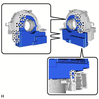
2. REMOVE STEERING SENSOR
| (a) Disengage the 6 claws and 2 pins, and remove the steering sensor from the spiral cable sub-assembly. NOTICE: Do not damage the claws and pins of the spiral cable sub-assembly. |
|
READ NEXT:
 Components
COMPONENTS ILLUSTRATION *1 INSTRUMENT CLUSTER FINISH PANEL ASSEMBLY *2 VSC OFF SWITCH
Inspection
INSPECTION PROCEDURE 1. INSPECT VSC OFF SWITCH (a) Make sure that there is no looseness at the locking part and the connecting part of the connector. OK: The connector is securely connected.
SEE MORE:
Removal
REMOVAL CAUTION / NOTICE / HINT The necessary procedures (adjustment, calibration, initialization or registration) that must be performed after parts are removed and installed, or replaced during HV battery removal/installation are shown below. Necessary Procedures After Parts Removed/Installed/Repl
Diagnostic Trouble Code Chart
DIAGNOSTIC TROUBLE CODE CHART Parking Support Alert System DTC No. Detection Item Link C1611 ECU Malfunction C168D Vehicle Information Unmatched C1AE1 Front Left Sensor Malfunction C1AE2 Front Left Center Sensor C1AE3 Front Right Center Sensor
