Lexus ES: Removal
REMOVAL
CAUTION / NOTICE / HINT
The necessary procedures (adjustment, calibration, initialization or registration) that must be performed after parts are removed and installed, or replaced during HV battery removal/installation are shown below.
Necessary Procedures After Parts Removed/Installed/Replaced| Replaced Part or Performed Procedure | Necessary Procedure | Effect/Inoperative Function when Necessary Procedure not Performed | Link |
|---|---|---|---|
|
*: When performing learning using the Techstream.
Click here | |||
| Auxiliary battery terminal is disconnected/reconnected | Perform steering sensor zero point calibration | Lane Control System | |
| Pre-collision System | |||
| Parking Support Brake System* | |||
| Lighting System | |||
| Memorize steering angle neutral point | Parking assist monitor system | | |
| Panoramic view monitor system | | ||
| Initialize power trunk lid system | Power Trunk Lid System | | |
| Replacement of HV battery | Battery status info update | HV battery status information cannot be updated | |
| Replacement of hybrid battery terminal block | Perform high voltage fuse accumulated load history reset | DTCs are stored | |
CAUTION:
-
Orange wire harnesses and connectors indicate high-voltage circuits. To prevent electric shock, always follow the procedure described in the repair manual.
.png)
Click here
.gif)
-
To prevent electric shock, wear insulated gloves when working on wire harnesses and components of the high voltage system.
.png)
NOTICE:
-
When the cable is disconnected from the negative (-) auxiliary battery terminal, some systems need to be initialized after the cable is reconnected.
Click here
- If the HV battery has been struck or dropped, replace it.
-
When connecting a connector to the HV battery, confirm that the connector is securely connected through the following:
- Push the connector until a click sound is heard.
- Visually check and confirm that the connector is securely connected by pulling on it.
-
Make sure to insulate the high-voltage connectors and terminals of the HV battery with insulating tape after removing it.
If the HV battery is stored without insulating the connectors and terminals, electric shock or fire may result.
- When performing repairs around the HV battery, such as using a tap, do not allow metal shavings to enter the HV battery.
- Do not touch any high voltage wire harnesses, connectors or parts with bare hands.
-
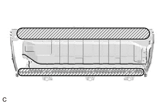
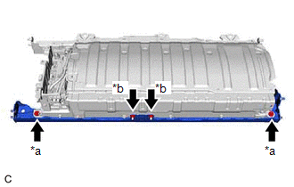
Hold the areas shown in the illustration and lift the HV battery.
- Do not allow foreign matter, such as grease or oil, to adhere to the bolts or nuts of the HV battery.
-
Do not put your hands into the openings of the HV battery.
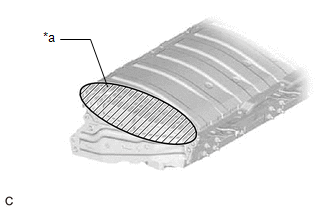
*a
Opening
- When removing/installing/moving the HV battery, make sure not to tilt it more than 80°.
- Do not climb on top of or stand on the HV battery.
- Do not allow any foreign matter or water to enter the HV battery.
- If any bolts, nuts or clips are dropped into the HV battery, make sure to remove them.
- After the power switch is turned off, the radio receiver assembly records various types of memory and settings. As a result, after turning the power switch off, make sure to wait at least 85 seconds before disconnecting the cable from the negative (-) auxiliary battery terminal. (for Audio and Visual System)
- After the power switch is turned off, the radio receiver assembly records various types of memory and settings. As a result, after turning the power switch off, make sure to wait at least 85 seconds before disconnecting the cable from the negative (-) auxiliary battery terminal. (for Navigation System)
HINT:
When disposing of an HV battery, make sure to return it through an authorized collection agent who is capable of handling it safely. If the HV battery is returned via the manufacturer specified route, it will be returned properly and in a safe manner by an authorized collection agent.
PROCEDURE
1. PRECAUTION
Click here
2. REMOVE SERVICE PLUG GRIP
Click here
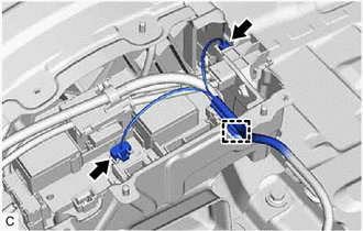
3. DISCONNECT ENGINE ROOM MAIN WIRE
Click here
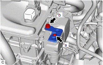
4. REMOVE CONNECTOR COVER ASSEMBLY
Click here
5. CHECK TERMINAL VOLTAGE
Click here
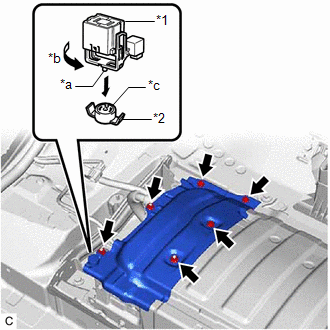
6. INSTALL CONNECTOR COVER ASSEMBLY
CAUTION:
Be sure to wear insulated gloves.
| (a) Using a T25 "TORX" socket wrench, install the connector cover assembly to the inverter with converter assembly with the bolt (A). Torque: 4.5 N·m {46 kgf·cm, 40 in·lbf} NOTICE: Do not touch the waterproof seal of the connector cover assembly. |
|
(b) Install the bolt (B).
Torque:
8.0 N·m {82 kgf·cm, 71 in·lbf}
7. CONNECT ENGINE ROOM MAIN WIRE
Click here
8. REMOVE BATTERY COOLING BLOWER ASSEMBLY
Click here
9. REMOVE NO. 1 HV BATTERY COVER PANEL RH
CAUTION:
Be sure to wear insulated gloves.
| (a) Using the service plug grip, remove the battery cover lock striker. HINT: Insert the projection of the service plug grip and turn the button of the battery cover lock striker counterclockwise to release the lock. |
|
(b) Remove the 3 bolts, 3 nuts and No. 1 HV battery cover panel RH from the HV battery.
10. DISCONNECT HV FLOOR UNDER WIRE
CAUTION:
Be sure to wear insulated gloves.
| (a) Disconnect the 2 HV battery junction block assembly connectors. NOTICE: Insulate each disconnected high-voltage connector with insulating tape. Wrap the connector from the wire harness side to the end of the connector. |
|
.png)
(b) Disconnect the shield ground from the HV battery.
| (c) Disconnect the floor wire connector. |
|
.png)
11. DISCONNECT FLOOR WIRE
CAUTION:
Be sure to wear insulated gloves.
| (a) Disengage the clamp. |
|
(b) Disconnect the electric vehicle battery plug assembly connector.
(c) Disconnect the HV battery junction block assembly connector.
12. REMOVE NO. 2 INDOOR ELECTRICAL KEY ANTENNA ASSEMBLY
Click here
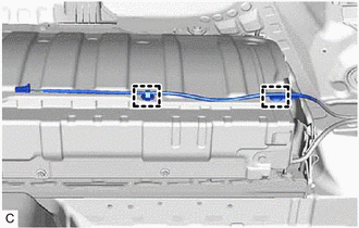
13. DISCONNECT FLOOR WIRE
CAUTION:
Be sure to wear insulated gloves.
| (a) Disengage the 2 clamps to disconnect the floor wire. |
|
14. REMOVE NO. 1 HYBRID BATTERY EXHAUST DUCT
CAUTION:
Be sure to wear insulated gloves.
| (a) Remove the clip. |
|
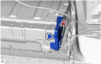
(b) Disengage the claw to remove the No. 1 hybrid battery exhaust duct from the HV battery.
15. DISCONNECT FLOOR WIRE
CAUTION:
Be sure to wear insulated gloves.
| (a) Disengage the clamp. |
|
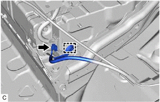
(b) Disconnect the battery voltage sensor connector.
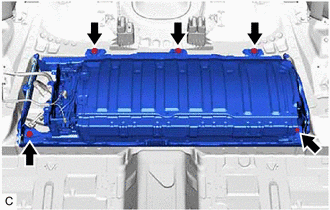
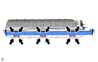
16. REMOVE HV BATTERY
CAUTION:
Be sure to wear insulated gloves.
| (a) Remove the 5 bolts and HV battery from the vehicle body. NOTICE:
|
|
17. REMOVE NO. 4 HV BATTERY SHIELD SUB-ASSEMBLY
CAUTION:
Be sure to wear insulated gloves.
| (a) Remove the 4 nuts and No. 4 HV battery shield sub-assembly from the HV battery. |
|
18. REMOVE NO. 3 HV BATTERY SHIELD SUB-ASSEMBLY
CAUTION:
Be sure to wear insulated gloves.
| (a) Remove the 4 nuts and No. 3 HV battery shield sub-assembly from the HV battery. |
|
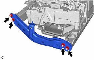
19. REMOVE NO. 4 HV BATTERY END PLATE SUB-ASSEMBLY
CAUTION:
Be sure to wear insulated gloves.
| (a) Remove the 2 bolts, 2 nuts and No. 4 HV battery end plate sub-assembly from the HV battery. |
|
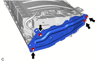
20. REMOVE NO. 5 HV BATTERY END PLATE SUB-ASSEMBLY
CAUTION:
Be sure to wear insulated gloves.
| (a) Remove the 12 nuts and No. 5 HV battery end plate sub-assembly from the HV battery. |
|
21. REMOVE UPPER HV BATTERY COVER SUB-ASSEMBLY
Click here
22. REMOVE NO. 1 HV BATTERY SHIELD PANEL
Click here
23. REMOVE BATTERY VOLTAGE SENSOR
Click here
24. REMOVE HYBRID BATTERY TERMINAL BLOCK
Click here
25. REMOVE HV BATTERY JUNCTION BLOCK ASSEMBLY
Click here
26. REMOVE NO. 2 HYBRID BATTERY SHIELD SUB-ASSEMBLY
Click here
27. REMOVE NO. 1 HV BATTERY INTAKE DUCT LH
Click here
READ NEXT:
 Installation
INSTALLATION PROCEDURE 1. INSTALL NO. 1 HV BATTERY INTAKE DUCT LH Click here 2. INSTALL NO. 2 HYBRID BATTERY SHIELD SUB-ASSEMBLY Click here 3. INSTALL HV BATTERY JUNCTION BLOCK ASSEMBLY Click here
Charging
CHARGING CAUTION / NOTICE / HINT The necessary procedures (adjustment, calibration, initialization or registration) that must be performed after parts are removed and installed, or replaced when charg
SEE MORE:
System Description
SYSTEM DESCRIPTION DESCRIPTION (a) Safety Connect performs ACN (Automatic Collision Notification), manual emergency calling, stolen vehicle tracking and roadside assistance service by, audio and data communications between the vehicle and call center through a cellular phone network. As shown in the
Problem Symptoms Table
PROBLEM SYMPTOMS TABLE HINT:
Use the table below to help determine the cause of problem symptoms. If multiple suspected areas are listed, the potential causes of the symptoms are listed in order of probability in the "Suspected Area" column of the table. Check each symptom by checking the suspect
