Lexus ES: Removal
REMOVAL
CAUTION / NOTICE / HINT
The necessary procedures (adjustment, calibration, initialization, or registration) that must be performed after parts are removed, installed, or replaced during brake actuator assembly removal/installation are shown below.
Necessary Procedures After Parts Removed/Installed/Replaced| Replaced Part or Performed Procedure | Necessary Procedure | Effect/Inoperative Function when Necessary Procedure not Performed | Link |
|---|---|---|---|
|
*: When performing learning using the Techstream.
Click here | |||
| Auxiliary battery terminal is disconnected/reconnected | Perform steering sensor zero point calibration | Lane Control System | |
| Pre-collision System | |||
| Parking Support Brake System* | |||
| Lighting System | |||
| Memorize steering angle neutral point | Parking Assist Monitor System | | |
| Panoramic View Monitor System | | ||
| Initialize power trunk lid system | Power Trunk Lid System | | |
| Replacement of brake actuator assembly |
|
| for Initialization: for Calibration: |
| Operate the electric parking brake switch assembly | Parking brake indicator light (red) blinks when the power switch is first turned on (IG) | | |
NOTICE:
- After the power switch is turned off, the radio receiver assembly records various types of memory and settings. As a result, after turning the power switch off, make sure to wait at least 85 seconds before disconnecting the cable from the negative (-) auxiliary battery terminal. (for Audio and Visual System)
- After the power switch is turned off, the radio receiver assembly records various types of memory and settings. As a result, after turning the power switch off, make sure to wait at least 85 seconds before disconnecting the cable from the negative (-) auxiliary battery terminal. (for Navigation System)
CAUTION / NOTICE / HINT
NOTICE:
While the auxiliary battery is connected, even if the power switch is off, the brake control system activates when the brake pedal is depressed or any door courtesy switch turns on. Therefore, when servicing the brake system components, do not operate the brake pedal or open/close the doors while the auxiliary battery is connected.
PROCEDURE
1. REMOVE BRAKE BOOSTER PUMP ASSEMBLY
Click here .gif)
2. REMOVE FRONT WHEEL RH
Click here
3. SEPARATE FRONT STABILIZER LINK ASSEMBLY RH
HINT:
Use the same procedure as for the LH side.
Click here
4. REMOVE BRAKE ACTUATOR WITH BRACKET
(a) Release the lock lever and disconnect the connector from the brake actuator assembly.
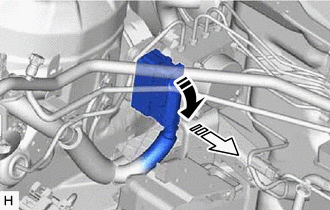
.png) | Release the lock lever |
.png) | Disconnect the connector |
NOTICE:
Be careful not to allow any brake fluid to enter the connector.
| (b) Use tags or make a memo to identify the places to reconnect the brake lines. |
|
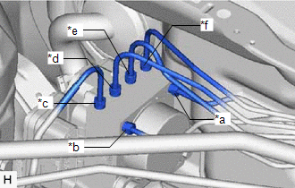
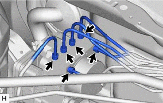
| (c) Using a union nut wrench, disconnect the 6 brake lines from the brake actuator assembly. NOTICE:
|
|
(d) Apply protective tape to the vehicle body as shown in the illustration.
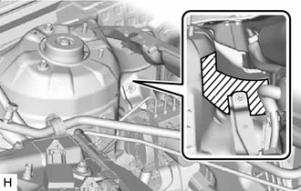
.png) | Protective Tape |
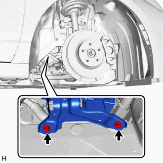
| (e) Remove the 2 bolts. HINT: Insert the tool from the bottom of the vehicle. |
|
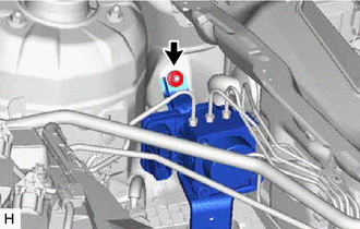
| (f) Remove the nut. |
|
(g) Remove the brake actuator with bracket as shown in the illustration.
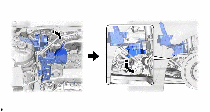
NOTICE:
- Do not kink or damage the brake lines.
- Do not allow any foreign matter such as dirt or dust to enter the brake lines from the connecting parts.
- Be careful not to allow any brake fluid to enter the connector.
- Do not hold the brake actuator assembly by the connector.
- Do not drop the brake actuator with bracket when carrying it.
HINT:
Remove the brake actuator with bracket while avoiding the brake lines.
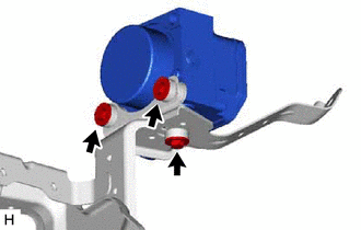
5. REMOVE BRAKE ACTUATOR ASSEMBLY
| (a) Remove the 3 bolts and brake actuator assembly from the brake actuator bracket assembly. NOTICE:
|
|
6. REMOVE BRAKE ACTUATOR BOLT CUSHION
| (a) Remove the 3 brake actuator case collars from the brake actuator bolt cushions. |
|
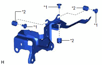
(b) Remove the 3 brake actuator bolt cushions from the brake actuator bracket assembly.
READ NEXT:
 Brake Hold Switch
ComponentsCOMPONENTS ILLUSTRATION *1 BRAKE HOLD SWITCH (NO. 2 COMBINATION SWITCH ASSEMBLY) *2 REAR UPPER CONSOLE PANEL SUB-ASSEMBLY InspectionINSPECTION PROCEDURE 1. INSPECT BRAKE HOLD
Components
COMPONENTS ILLUSTRATION *1 NO. 1 INSTRUMENT PANEL UNDER COVER SUB-ASSEMBLY - - ILLUSTRATION *1 BRAKE PEDAL STROKE SENSOR ASSEMBLY *2 BRAKE PEDAL SUPPORT ASSEMBLY N*m (kgf
SEE MORE:
ANC ECU EEPROM Data Memory Failure (B1AA044)
DESCRIPTION This DTC is stored when a malfunction occurs in the stereo component equalizer assembly. DTC No. Detection Item DTC Detection Condition Trouble Area B1AA044 ANC ECU EEPROM Data Memory Failure Stereo component equalizer assembly malfunction Stereo component equalizer as
Back Camera Disconnected (C1622)
DESCRIPTION This DTC is stored if the radio receiver assembly judges that the signals or signal lines between the rear television camera assembly and the multi-display assembly are not normal as a result of its self check. DTC No. Detection Item DTC Detection Condition Trouble Area C162
