Lexus ES: Components
COMPONENTS
ILLUSTRATION
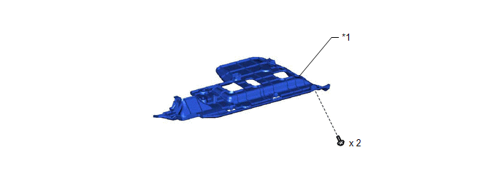
| *1 | NO. 1 INSTRUMENT PANEL UNDER COVER SUB-ASSEMBLY | - | - |
ILLUSTRATION
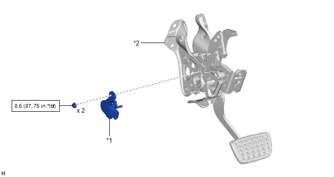
| *1 | BRAKE PEDAL STROKE SENSOR ASSEMBLY | *2 | BRAKE PEDAL SUPPORT ASSEMBLY |
.png) | N*m (kgf*cm, ft.*lbf): Specified torque | - | - |
READ NEXT:
 Installation
INSTALLATION PROCEDURE 1. INSPECT AND ADJUST BRAKE PEDAL HEIGHT Click here 2. INSTALL BRAKE PEDAL STROKE SENSOR ASSEMBLY NOTICE:
Do not drop the brake pedal stroke sensor assembly.
If the brak
Removal
REMOVAL CAUTION / NOTICE / HINT The necessary procedures (adjustment, calibration, initialization, or registration) that must be performed after parts are removed, installed, or replaced during brake
SEE MORE:
Customize Parameters
CUSTOMIZE PARAMETERS DRIVE MODE CUSTOMIZATION (w/ Adaptive Variable Suspension System) When the drive mode is switched to "CUSTOM" mode using the drive mode select switch (combination switch assembly), the vehicle settings can be changed on the multi-display. HINT: Differing to that of "ECO", "SPORT
Data List / Active Test
DATA LIST / ACTIVE TEST DATA LIST NOTICE: In the table below, the values listed under "Normal Condition" are reference values. Do not depend solely on these reference values when deciding whether a part is faulty or not. HINT: Using the Techstream to read the Data List allows the values or states of
© 2016-2026 Copyright www.lexguide.net
