Lexus ES: Brake Hold Switch
Components
COMPONENTS
ILLUSTRATION
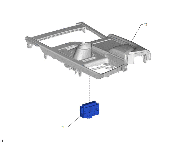
| *1 | BRAKE HOLD SWITCH (NO. 2 COMBINATION SWITCH ASSEMBLY) | *2 | REAR UPPER CONSOLE PANEL SUB-ASSEMBLY |
Inspection
INSPECTION
PROCEDURE
1. INSPECT BRAKE HOLD SWITCH (NO. 2 COMBINATION SWITCH ASSEMBLY)
| (a) Make sure that there is no looseness in the locking part and the connecting part of the connector. OK: The connector is securely connected. |
|
(b) Disconnect the brake hold switch (No. 2 combination switch assembly) connector.
(c) Check both the connector case and the terminal for deformation and corrosion.
OK:
No deformation or corrosion.
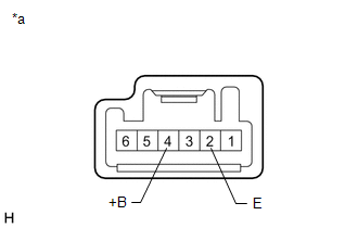
(d) Measure the resistance according to the value(s) in the table below.
Standard Resistance:
| Tester Connection | Condition | Specified Condition |
|---|---|---|
| 4 (+B) - 2 (E) | Switch pushed | Below 1 Ω |
| 4 (+B) - 2 (E) | Switch not pushed | 10 kΩ or higher |
HINT:
If the result is not as specified, replace the brake hold switch (No. 2 combination switch assembly).
Removal
REMOVAL
PROCEDURE
1. REMOVE REAR UPPER CONSOLE PANEL SUB-ASSEMBLY
Click here .gif)
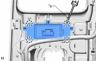
2. REMOVE BRAKE HOLD SWITCH (NO. 2 COMBINATION SWITCH ASSEMBLY)
| (a) Using a screwdriver with its tip wrapped with protective tape, disengage the 4 claws to remove the brake hold switch (No. 2 combination switch assembly) from the rear upper console panel sub-assembly. |
|
READ NEXT:
 Components
COMPONENTS ILLUSTRATION *1 NO. 1 INSTRUMENT PANEL UNDER COVER SUB-ASSEMBLY - - ILLUSTRATION *1 BRAKE PEDAL STROKE SENSOR ASSEMBLY *2 BRAKE PEDAL SUPPORT ASSEMBLY N*m (kgf
Installation
INSTALLATION PROCEDURE 1. INSPECT AND ADJUST BRAKE PEDAL HEIGHT Click here 2. INSTALL BRAKE PEDAL STROKE SENSOR ASSEMBLY NOTICE:
Do not drop the brake pedal stroke sensor assembly.
If the brak
SEE MORE:
Installation
INSTALLATION CAUTION / NOTICE / HINT HINT:
Use the same procedure for the RH side and LH side.
The following procedure is for the LH side.
PROCEDURE 1. INSTALL SIDE TURN SIGNAL LIGHT ASSEMBLY (a) Engage the 4 guides and 2 claws to install the side turn signal light assembly. 2. INSTALL OUTER
Components
COMPONENTS ILLUSTRATION *1 FRONT FLOOR COVER LH *2 FRONT FLOOR COVER RH N*m (kgf*cm, ft.*lbf): Specified torque - - ILLUSTRATION *1 CENTER FLOOR CROSSMEMBER BRACE *2 FRONT CENTER FLOOR BRACE N*m (kgf*cm, ft.*lbf): Specified torque - - ILLUSTRATION
