Lexus ES: Removal
REMOVAL
CAUTION / NOTICE / HINT
The necessary procedures (adjustment, calibration, initialization, or registration) that must be performed after parts are removed and installed, or replaced during side television camera assembly removal/installation are shown below.
Necessary Procedure After Parts Removed/Installed/Replaced (for HV Model)| Replaced Part or Performed Procedure | Necessary Procedure | Effect/Inoperative Function When Necessary Procedures are not Performed | Link |
|---|---|---|---|
| Side television camera view adjustment | Panoramic View Monitor System | |
| Replaced Part or Performed Procedure | Necessary Procedure | Effect/Inoperative Function When Necessary Procedures are not Performed | Link |
|---|---|---|---|
| Side television camera view adjustment | Panoramic View Monitor System | |
HINT:
- Use the same procedure for the RH side and LH side.
- The following procedure is for the LH side.
PROCEDURE
1. REMOVE OUTER MIRROR
Click here .gif)
2. REMOVE OUTER MIRROR COVER ASSEMBLY
Click here
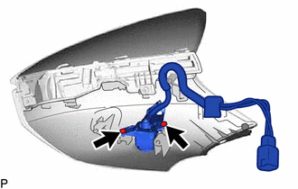
3. REMOVE SIDE TELEVISION CAMERA ASSEMBLY
| (a) Remove the 2 screws and side television camera assembly. |
|
READ NEXT:
 Components
COMPONENTS ILLUSTRATION *1 REAR TELEVISION CAMERA ASSEMBLY *2 TELEVISION CAMERA ASSEMBLY WITH WIRE *3 TELEVISION CAMERA WIRE - -
Installation
INSTALLATION PROCEDURE 1. INSTALL REAR TELEVISION CAMERA ASSEMBLY 2. INSTALL TELEVISION CAMERA WIRE (a) Connect the connector to install the television camera wire. 3. INSTALL TELEVISION CAMERA ASSEMB
SEE MORE:
Washer Motor Circuit
DESCRIPTION When the windshield washer motor and pump assembly receives signals from the windshield wiper switch assembly it operates to spray washer fluid from the washer nozzle sub-assemblies. WIRING DIAGRAM CAUTION / NOTICE / HINT NOTICE:
Inspect the fuses for circuits related to this system
Outside Air Temperature Sensor (C1652)
DESCRIPTION When a malfunction signal sent from the air conditioning system via CAN communication is detected by the clearance warning ECU assembly, DTC C1652 is stored. DTC No. Detection Item DTC Detection Condition Trouble Area C1652 Outside Air Temperature Sensor Ambient temperat
