Lexus ES: Inspection
INSPECTION
CAUTION / NOTICE / HINT
NOTICE:
- When using a vise, place aluminum plates between the part and vise.
- When using a vise, do not overtighten it.
PROCEDURE
1. INSPECT REAR DRIVE SHAFT ASSEMBLY
| (a) Check that there is no excessive play in the radial direction of the outboard joint. |
|
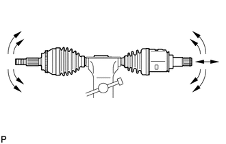
(b) Check that the inboard joint slides smoothly in the thrust direction.
(c) Check that there is no excessive play in the radial direction of the inboard joint.
(d) Check the boots for damage.
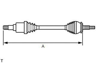
| (e) Check whether the drive shaft dimension (A) is within specification. Length (A): 749.1 to 759.1 mm (2.46 to 2.49 ft.) NOTICE: Keep the drive shaft assembly level during inspection. If the boots are stretched or contracted, correct them. |
|
READ NEXT:
 Installation
INSTALLATION CAUTION / NOTICE / HINT HINT:
Use the same procedure for the RH and LH sides.
The procedure listed below is for the LH side.
PROCEDURE 1. INSTALL REAR DRIVE SHAFT INBOARD JOINT SH
Reassembly
REASSEMBLY CAUTION / NOTICE / HINT NOTICE:
When using a vise, place aluminum plates between the part and vise.
When using a vise, do not overtighten it.
HINT:
Use the same procedure for the
Removal
REMOVAL CAUTION / NOTICE / HINT The necessary procedures (adjustment, calibration, initialization, or registration) that must be performed after parts are removed and installed, or replaced during rea
SEE MORE:
Diagnosis System
DIAGNOSIS SYSTEM DESCRIPTION When troubleshooting OBD II (On-Board Diagnostics) vehicles, the Techstream (complying with SAE J1978) must be connected to the DLC3 (Data Link Connector 3) of the vehicle. Various data in the vehicle's ECM (Engine Control Module) can be then read. OBD II regulations re
Engine Coolant Bypass Valve Circuit Short to Ground (P268111,P268115)
DESCRIPTION The flow shutting valve (for heater control) used for the variable cooling system is a magnet type valve that is closed when the engine is warming up to prevent coolant from flowing through the heater passage which reduces engine warm up time. DTC No. Detection Item DTC Detection
© 2016-2026 Copyright www.lexguide.net
