Lexus ES: Relay
On-vehicle Inspection
ON-VEHICLE INSPECTION
PROCEDURE
1. INSPECT H-LP LH RELAY
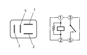
(a) Measure the resistance according to the value(s) in the table below.
Standard Resistance:
| Tester Connection | Condition | Specified Condition |
|---|---|---|
| 3 - 5 | Voltage not applied between terminals 1 and 2 | 10 kΩ or higher |
| 3 - 5 | Voltage applied between terminals 1 and 2 | Below 1 Ω |
If the result is not as specified, replace the H-LP LH relay.
2. INSPECT H-LP RH RELAY
(a) Measure the resistance according to the value(s) in the table below.
Standard Resistance:
| Tester Connection | Condition | Specified Condition |
|---|---|---|
| 3 - 5 | Voltage not applied between terminals 1 and 2 | 10 kΩ or higher |
| 3 - 5 | Voltage applied between terminals 1 and 2 | Below 1 Ω |
If the result is not as specified, replace the H-LP RH relay.
READ NEXT:
 Components
COMPONENTS ILLUSTRATION *A w/o Panoramic View Monitor System *B w/ Panoramic View Monitor System *1 OUTER MIRROR *2 OUTER MIRROR COVER ASSEMBLY *3 OUTER MIRROR LOWER COVER
Removal
REMOVAL CAUTION / NOTICE / HINT The necessary procedures (adjustment, calibration, initialization, or registration) that must be performed after parts are removed and installed, or replaced during sid
SEE MORE:
How To Proceed With Troubleshooting
CAUTION / NOTICE / HINT HINT:
Use the following procedure to troubleshoot the power mirror control system (w/o Memory).
*: Use the Techstream.
PROCEDURE 1. VEHICLE BROUGHT TO WORKSHOP
NEXT 2. CUSTOMER PROBLEM ANALYSIS HINT:
In troubleshooting, confirm th
Black Screen
PROCEDURE 1. CHECK DISPLAY SETTING (a) Check that the display is not in screen off mode. OK: The display setting is not in screen off mode. NG CHANGE SCREEN TO SCREEN ON MODE
OK 2. CHECK IMAGE QUALITY SETTING (a) Check that the screen color quality can be
© 2016-2026 Copyright www.lexguide.net
