Lexus ES: Recovery Inspection
CAUTION / NOTICE / HINT
CAUTION:
- When disposing of an HV supply stack sub-assembly, make sure to return it through an authorized collection agent who is capable of handling it safely. If it is returned via the manufacturer specified route, it will be returned properly and in a safe manner by an authorized collection agent.
- Before returning an HV supply stack sub-assembly, make sure to perform a pre-return inspection.
-
Accidents such as electric shock may result if an HV supply stack sub-assembly is discharged improperly and disposed or abandoned.
Therefore, make sure to return all HV supply stack sub-assemblies through an authorized collection agent.
- To reduce the risk of fire, HV supply stack sub-assemblies must not be stored in an area where they will be exposed to fire or high temperatures.
- If the temperature of an HV supply stack sub-assembly is high, leave it to cool down.
HINT:
In order to return an HV supply stack sub-assembly in a safe manner, it may be necessary to discharge it. The following pre-return inspection procedure can be used to determine whether or not it is necessary to discharge an HV supply stack sub-assembly the method that may be required.
PROCEDURE
| 1. | INSPECT FOR ELECTROLYTE LEAK |
CAUTION:
Be sure to wear insulated gloves and protective goggles.
(a) Inspect for electrolyte leaks after removing the HV supply stack sub-assembly.
OK:
No leak was found on the lower part of the battery outer case.
CAUTION:
- Perform this procedure in an area where the HV battery will not be exposed to fire.
- Do not touch the HV supply stack sub-assembly, unless absolutely necessary, as electrolyte may be leaking.
NOTICE:
If there is an electrolyte leak, make sure to wear insulated gloves and goggles and clean it using a piece of cloth. Do not leave electrolyte-contaminated cloths unattended. Dispose of them according to law or local regulations.
| NG | .gif) | DISCHARGING (WHEN USING THE SALT WATER SOLUTION) |
|
.gif)
| 2. | CHECK FOR DTCS |
(a) Check the previously recorded DTCs which resulted in replacement of the HV supply stack sub-assembly.
| Result | Proceed to |
|---|---|
| DTC record not available. | A |
| The HV supply stack sub-assembly was replaced due to a reason other than the DTCs listed in the following table. | B |
| The HV supply stack sub-assembly was replaced due to one of the DTCs listed in the following table. | C |
| DTC No. |
|---|
| P1A6017 |
| P31AA17 |
| P0C3000 |
| P31B300 |
| P1C7D49 |
| B | | GO TO STEP 5 |
| C | | GO TO STEP 6 |
|
| 3. | CHECK HV SUPPLY STACK SUB-ASSEMBLY VOLTAGE |
CAUTION:
Be sure to wear insulated gloves and protective goggles.
| (a) Measure the voltage according to the value(s) in the table below. Standard Voltage:
CAUTION: Make sure not to cross the probes of the electrical tester. |
|
| NG | | GO TO STEP 6 |
|
| 4. | INSULATION INSPECTION OF HV SUPPLY STACK SUB-ASSEMBLY |
CAUTION:
Be sure to wear insulated gloves and protective goggles.
| (a) Using a megohmmeter set to 500 V, measure the insulation resistance according to the value(s) in the table below. NOTICE: Be sure to set the megohmmeter to 500 V when performing this test. Using a setting higher than 500 V can result in damage to the component being inspected. Standard Resistance:
|
|
| NG | | GO TO STEP 6 |
|
| 5. | HV SUPPLY STACK SUB-ASSEMBLY VISUAL CHECK |
CAUTION:
Be sure to wear insulated gloves and protective goggles.
(a) Check that the HV supply stack sub-assembly is not deformed or damaged.
OK:
The HV supply stack sub-assembly is not deformed or damaged.
| OK | | RETURN HV SUPPLY STACK SUB-ASSEMBLY |
| NG | | GO TO STEP 6 |
| 6. | HV SUPPLY STACK SUB-ASSEMBLY CONNECTORS VISUAL CHECK |
CAUTION:
Be sure to wear insulated gloves and protective goggles.
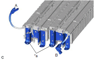
(a) Check that the orange connectors connected to the battery ECU assembly are not deformed or damaged.
OK:
The connectors are not deformed or damaged.
HINT:
If any of the connectors are damaged, a Li-ion battery discharger will not be able to be connected to the HV supply stack sub-assembly. Soak the HV supply stack sub-assembly in a saltwater solution to discharge it.
| OK | | DISCHARGING (WHEN USING THE LI-ION BATTERY DISCHARGER) |
| NG | | DISCHARGING (WHEN USING THE SALT WATER SOLUTION) |
READ NEXT:
 Discharging
DISCHARGING PROCEDURE 1. DISCHARGING (WHEN USING THE LI-ION BATTERY DISCHARGER) CAUTION: Be sure to wear insulated gloves and protective goggles. NOTICE: Make sure to observe the following points whe
Components
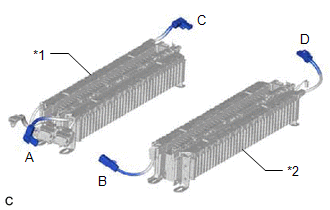
COMPONENTS ILLUSTRATION *1 UPPER HV BATTERY COVER SUB-ASSEMBLY *2 HV BATTERY JUNCTION BLOCK ASSEMBLY *3 ELECTRIC VEHICLE BATTERY PLUG ASSEMBLY *4 WIRING HARNESS PROTECTOR N*
SEE MORE:
Position Initialization Incomplete (Fr Shade) (B2348)
DESCRIPTION This DTC is stored when the roof sunshade ECU (sliding roof drive gear assembly) has not been initialized. DTC No. Detection Item DTC Detection Condition Trouble Area B2348 Position Initialization Incomplete (Fr Shade) Roof sunshade ECU (sliding roof drive gear assembly)
Steering Position Sensor (B2414)
DESCRIPTION The headlight ECU sub-assembly LH receives steering angle signals from the steering sensor via CAN communication and performs light control. for LED Type Turn Signal Light DTC No. Detection Item DTC Detection Condition Trouble Area DTC Output from B2414 Steering Position
