Lexus ES: Reassembly
REASSEMBLY
CAUTION / NOTICE / HINT
HINT:
- Use the same procedure for the RH side and LH side.
- The following procedure is for the LH side.
PROCEDURE
1. INSTALL HEADLIGHT SEAL (for TMC Made)
Click here .gif)
2. INSTALL HEADLIGHT BRACKET (for TMC Made)
| (a) Engage the 2 guides. |
|
.png)
(b) Install the headlight bracket with the 2 screws.
(c) Engage the claw to connect the No. 2 headlight cord.
3. INSTALL HEADLIGHT UNIT ASSEMBLY (for TMC Made)
4. INSTALL HEADLIGHT CORD (for TMC Made)
| (a) Engage the 3 clamps to install the headlight cord. |
|
.png)
(b) Connect the connector.
5. INSTALL FRONT SIDE MARKER LIGHT BULB
(a) Install the front side marker light bulb to the headlight cord.
(b) Turn the headlight cord with the front side marker light bulb as shown in the illustration to install them as a unit.
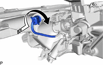
.png) | Install in this Direction |
6. INSTALL FRONT TURN SIGNAL LIGHT BULB
(a) Install the front turn signal light bulb to the headlight cord.
(b) Turn the headlight cord with the front turn signal light bulb as shown in the illustration to install them as a unit.
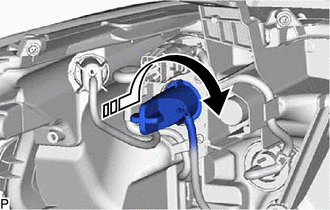
| | Install in this Direction |
7. INSTALL NO. 2 HEADLIGHT FITTING RIM (for TMC Made)
Click here
8. INSTALL HEADLIGHT RIM (for TMC Made)
Click here
9. INSTALL HEADLIGHT GASKET
Click here
10. INSTALL HEADLIGHT ECU SUB-ASSEMBLY
Click here
READ NEXT:
 Installation
INSTALLATION CAUTION / NOTICE / HINT HINT:
Use the same procedure for the RH side and LH side.
The following procedure is for the LH side.
PROCEDURE 1. INSTALL HEADLIGHT ASSEMBLY Click here
Repair
REPAIR CAUTION / NOTICE / HINT HINT:
Use the same procedure for the RH side and LH side.
The following procedure is for the LH side.
If the installation area of the headlight assembly is damage
SEE MORE:
Confirm Cellular Phone Functionality
PROCEDURE 1. CHECK CUSTOMER'S CELLULAR PHONE COMPATIBILITY (a) Check if the cellular phone is compatible (Refer to http://www.lexus.com/MobileLink/). Result Proceed to Cellular phone is compatible. A Cellular phone is not compatible. B HINT: It is important to check the
How To Proceed With Troubleshooting
CAUTION / NOTICE / HINT HINT: *: Use the Techstream. PROCEDURE 1. VEHICLE BROUGHT TO WORKSHOP
NEXT 2. CUSTOMER PROBLEM ANALYSIS
NEXT 3. CONNECT TECHSTREAM TO DLC3* HINT: If the display indicates a communication malfunction, inspect the DLC
