Lexus ES: Reassembly
REASSEMBLY
PROCEDURE
1. INSTALL FRONT BUMPER SIDE SUPPORT LH
(a) Engage the clip as shown in the illustration.
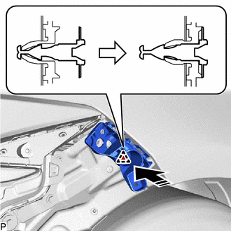
.png) | Install in this Direction |
| (b) Install the front bumper side support LH with the bolt. Torque: 5.4 N·m {55 kgf·cm, 48 in·lbf} |
|
.png)
2. INSTALL FRONT BUMPER SIDE SUPPORT RH
HINT:
Use the same procedure as for the LH side.
3. INSTALL FRONT BUMPER REINFORCEMENT SUB-ASSEMBLY
(a) Install the front bumper reinforcement sub-assembly with the 6 bolts as shown in the illustration.
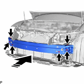
| | Install in this Direction |
Torque:
43 N·m {438 kgf·cm, 32 ft·lbf}
| (b) Engage the 4 clamps. |
|
.png)
(c) Install the headlight assembly LH.
Click here .gif)
(d) Install the headlight assembly RH.
HINT:
Use the same procedure as for the LH side.
4. INSTALL NO. 2 FRONT BUMPER MOUNTING BRACKET
(a) Engage the 8 claws as shown in the illustration.
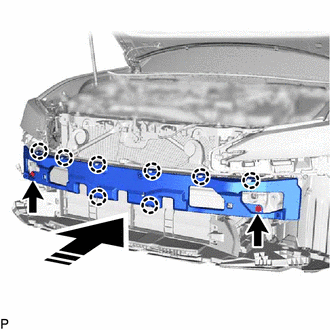
| | Install in this Direction |
(b) Install the No. 2 front bumper mounting bracket with the 2 bolts.
Torque:
43 N·m {438 kgf·cm, 32 ft·lbf}
5. INSTALL FRONT BUMPER ENERGY ABSORBER
(a) Engage the 2 guides as shown in the illustration.
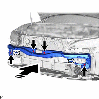
| | Install in this Direction |
(b) Install the front bumper energy absorber with 4 new clips.
6. INSTALL FRONT FENDER LINER RETAINER
(a) Engage the 3 claws to install the 3 front fender liner retainers as shown in the illustration.
| | Install in this Direction |
HINT:
Use the same procedure for the RH side and LH side.
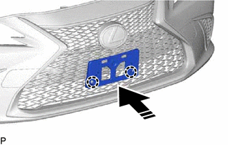
7. INSTALL INSIDE RADIATOR GRILLE (for TMC Made)
(a) for Bar Type Radiator Grille:
(1) Engage the 4 guides and 13 claws.
.png)
| (2) Install the inside radiator grille with 4 new spring nuts. |
|
.png)
(b) for Mesh Type Radiator Grille:
(1) Engage the 17 guides.
.png)
(2) Install the inside radiator grille with 17 new spring nuts.
.png)
8. INSTALL LOWER RADIATOR GRILLE MOULDING
(a) Engage the 9 claws.
.png)
| (b) Install the lower radiator grille moulding with the screw. |
|
.png)
9. INSTALL RADIATOR GRILLE SIDE MOULDING LH
| (a) Engage the 4 guides and 2 claws to install the radiator grille side moulding LH. |
|
.png)
10. INSTALL RADIATOR GRILLE SIDE MOULDING RH
HINT:
Use the same procedure as for the LH side.
11. INSTALL UPPER RADIATOR GRILLE MOULDING
| (a) Engage the 6 guides and 2 claws to install the upper radiator grille moulding. |
|
.png)
12. INSTALL RADIATOR GRILLE SUB-ASSEMBLY (for Bar Type Radiator Grille)
(a) Engage the 16 guides and 22 claws.
.png)
(b) Install the outside radiator grille with the 16 screws.
.png)
13. INSTALL RADIATOR GRILLE SUB-ASSEMBLY (for Mesh Type Radiator Grille)
(a) Engage the 16 guides and 22 claws.
.png)
(b) Install the outside radiator grille with the 16 screws.
.png)
14. INSTALL RADIATOR GRILLE (OR FRONT PANEL) EMBLEM
| (a) Engage the claw. |
|
.png)
(b) Install the radiator grille (or front panel) emblem with the 2 screws.
15. INSTALL UPPER FRONT BUMPER RETAINER
HINT:
Use the same procedure for the RH side and LH side.
| (a) Engage the guide. |
|
.png)
(b) Install the upper front bumper retainer with the screw.
16. INSTALL UPPER RADIATOR GRILLE
(a) Engage the 4 guides.
.png)
(b) Install the upper radiator grille with the 8 screws.
.png)
17. INSTALL CENTER FRONT BUMPER SEAL
HINT:
When installing the center front bumper seal, heat the front bumper cover using a heat light.
Heating Temperature| Item | Temperature |
|---|---|
| Front Bumper Cover | 20 to 30°C (68 to 86°F) |
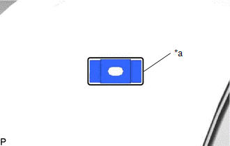
CAUTION:
- Do not touch the heat light and heated parts, touching the heat light may result in burns.
- Touching heated parts for a long time may result in burns.
.png)
| *a | Heated Part |
| *b | Heat Light |
NOTICE:
Do not heat the front bumper cover excessively.
(a) Clean the front bumper cover surface.
(1) Using a heat light, heat the front bumper cover surface.
(2) Remove any remaining double-sided tape from the front bumper cover.
(3) Wipe off any tape adhesive residue with cleaner.
(b) Remove the release paper from a new center front bumper seal.
HINT:
After removing the release paper, keep the exposed adhesive free from foreign matter.
(c) Attach the double-sided tape as shown in the illustration.
.png)
.png) | Double-sided Tape |
HINT:
Press the center front bumper seal firmly to install it.
(d) Engage the 5 clips to install the center front bumper seal.
18. INSTALL FRONT BUMPER HOLE COVER LH (for TMC Made)
| (a) Engage the hook. |
|
.png)
(b) Engage the 4 claws to install the front bumper hole cover LH.
19. INSTALL FRONT BUMPER HOLE COVER RH (for TMC Made)
HINT:
Use the same procedure as for the LH side.
20. INSTALL FRONT BUMPER SIDE MOULDING LH (for Bar Type Radiator Grille)
| (a) Engage the 3 guides and 4 claws to install the front bumper side moulding LH. |
|
.png)
21. INSTALL FRONT BUMPER SIDE MOULDING RH (for Bar Type Radiator Grille)
HINT:
Use the same procedure as for the LH side.
22. INSTALL RADIATOR GRILLE GARNISH SUB-ASSEMBLY LH (for Bar Type Radiator Grille)
| (a) Engage the 3 guides and 4 claws. |
|
.png)
| (b) Install the radiator grille garnish sub-assembly LH with the 3 screws. |
|
.png)
23. INSTALL RADIATOR GRILLE GARNISH SUB-ASSEMBLY RH (for Bar Type Radiator Grille)
HINT:
Use the same procedure as for the LH side.
24. INSTALL RADIATOR GRILLE GARNISH SUB-ASSEMBLY LH (for Mesh Type Radiator Grille)
| (a) Engage the 5 guides and claw. |
|
.png)
| (b) Install the radiator grille garnish sub-assembly LH with the 3 outside moulding retainers and 3 screws. |
|
.png)
25. INSTALL RADIATOR GRILLE GARNISH SUB-ASSEMBLY RH (for Mesh Type Radiator Grille)
HINT:
Use the same procedure as for the LH side.
26. INSTALL WIRING HARNESS CONNECTOR (w/o Panoramic View Monitor System)
| (a) Engage the clamp to install the wiring harness connector. |
|
.png)
27. INSTALL NO. 5 ENGINE ROOM WIRE (w/ Panoramic View Monitor System)
| (a) Engage the clamp to install the No. 5 engine room wire. |
|
.png)
28. INSTALL FRONT TELEVISION CAMERA ASSEMBLY (w/ Panoramic View Monitor System)
Click here
29. INSTALL MILLIMETER WAVE RADAR SENSOR ASSEMBLY (w/ Pre-collision System)
Click here
30. INSTALL WIRING HARNESS CONNECTOR (w/o Parking Support Alert System)
| (a) Engage the clamp to install the wiring harness connector. |
|
.png)
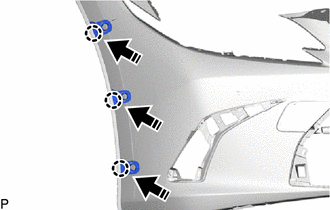
31. INSTALL ULTRASONIC SENSOR CLIP (w/ Parking Support Alert System)
HINT:
- Use the same procedure for the RH side and LH side.
- When installing the ultrasonic sensor clip, heat the front bumper cover using a heat light.
| Item | Temperature |
|---|---|
| Front Bumper Cover | 20 to 30°C (68 to 86°F) |
CAUTION:
- Do not touch the heat light and heated parts, touching the heat light may result in burns.
- Touching heated parts for a long time may result in burns.
| *a | Heated Part |
| *b | Heat Light |
NOTICE:
Do not heat the front bumper cover excessively.
(a) Clean the front bumper cover surface.
(1) Using a heat light, heat the front bumper cover surface.
(2) Remove any remaining double-sided tape from the front bumper cover.
(3) Wipe off any tape adhesive residue with cleaner.
(b) Using a brush or felt, apply primer or equivalent to the ultrasonic sensor clip installation area.
 | Primer |
NOTICE:
- Use a clean brush or felt.
- Do not touch the front bumper cover until the primer has dried.
(c) Remove the release paper from a new ultrasonic sensor clip.
HINT:
After removing the release paper, keep the exposed adhesive free from foreign matter.
| (d) Install the ultrasonic sensor clip as shown in the illustration. HINT: Press the ultrasonic sensor clip firmly to install it. |
|
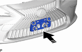
32. INSTALL NO. 4 ENGINE ROOM WIRE (w/ Parking Support Alert System)
(a) Engage the 10 clamps to install the No. 4 engine room wire.
.png)
33. INSTALL FRONT CORNER ULTRASONIC SENSOR RETAINER (w/ Parking Support Alert System)
Click here
HINT:
Use the same procedure for the RH side and LH side.
34. INSTALL FRONT CORNER ULTRASONIC SENSOR (w/ Parking Support Alert System)
Click here
HINT:
Use the same procedure for the RH side and LH side.
35. INSTALL FRONT CENTER ULTRASONIC SENSOR (w/ Parking Support Alert System)
Click here
HINT:
Use the same procedure for the RH side and LH side.
36. INSTALL SMOG VENTILATION SENSOR
Click here
37. INSTALL FRONT BUMPER EXTENSION MOUNTING BRACKET (for Bar Type Radiator Grille)
(a) Engage the 4 claws as shown in the illustration.
| | Install in this Direction |
| (b) Install the front bumper extension mounting bracket with the 2 screws. |
|
.png)
38. INSTALL FRONT BUMPER EXTENSION MOUNTING BRACKET (for Mesh Type Radiator Grille)
(a) Engage the 2 claws as shown in the illustration.
| | Install in this Direction |
| (b) Install the front bumper extension mounting bracket with the 2 screws. |
|
.png)
READ NEXT:
 Installation
INSTALLATION CAUTION / NOTICE / HINT HINT: When the front bumper is damaged or deformed due to an accident or contact with other objects, etc., or if the bumper installation area of the vehicle body h
Components
COMPONENTS ILLUSTRATION *A for Driver Side *B for Front Passenger Side *1 COURTESY LIGHT ASSEMBLY *2 FRONT DOOR TRIM BOARD SUB-ASSEMBLY *3 MULTIPLEX NETWORK MASTER SWITCH ASS
SEE MORE:
Dtc Check / Clear
DTC CHECK / CLEAR CHECK DTC (a) Connect the Techstream to the DLC3. (b) Turn the engine switch on (IG). (c) Turn the Techstream on. (d) Enter the following menus: Body Electrical / (desired system) / Trouble Codes. Body Electrical > Master Switch > Trouble Codes Body Electrical > D-Door Mot
Dtc Check / Clear
DTC CHECK / CLEAR CHECK DTC (a) Turn the engine switch off. (b) Connect the Techstream to the DLC3. (c) Turn the engine switch on (IG). (d) Turn the Techstream on. (e) Enter the following menus: Body Electrical / Tilt & Telescopic / Trouble Codes. Body Electrical > Tilt&Telescopic > Tr
