Lexus ES: Installation
INSTALLATION
CAUTION / NOTICE / HINT
HINT:
When the front bumper is damaged or deformed due to an accident or contact with other objects, etc., or if the bumper installation area of the vehicle body has been repaired, it is necessary to perform millimeter wave radar sensor adjustment.
Click here .gif)
PROCEDURE
1. INSTALL FRONT BUMPER ASSEMBLY
(a) Move the front bumper assembly into position and engage the 4 guides and 4 claws as shown in the illustration.
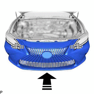
.png) | Install in this Direction |
(b) Install the 4 bolts.
(c) Pull back the side of the front bumper assembly and connect the connector.
NOTICE:
Do not apply excessive force when pulling back the front bumper assembly.
(d) w/ Pre-collision System:
(1) Connect the connector.
(e) Connect the 2 connectors.
(f) Engage the guide and 7 claws as shown in the illustration.
HINT:
Use the same procedure for the RH side and LH side.
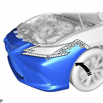
| | Install in this Direction |
(g) Install the 8 screws.
(h) Install the front bumper side mounting bracket with the screw.
HINT:
Use the same procedure for the RH side and LH side.
(i) Install the clip to install the front bumper assembly.
HINT:
Use the same procedure for the RH side and LH side.
(j) Engage the 6 claws to install the 3 pin hold clips as shown in the illustration.
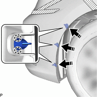
| | Install in this Direction |
HINT:
Use the same procedure for the RH side and LH side.
2. INSTALL COOL AIR INTAKE DUCT SEAL
(a) Engage the guide as shown in the illustration.
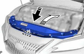
| | Install in this Direction (1) |
.png) | Install in this Direction (2) |
(b) Install the cool air intake duct seal with the 7 clips.
3. PERFORM CALIBRATION (w/ Panoramic View Monitor System)
for HV Model:
Click here
for Gasoline Model:
Click here
4. PERFORM CALIBRATION (w/ Parking Support Brake System)
for HV Model:
Click here
for Gasoline Model:
Click here
5. ADJUST HEADLIGHT AIMING
HINT:
Perform this procedure only when replacement of the front bumper reinforcement is necessary.
for LED Type Turn Signal Light:
Click here
for Bulb Type Turn Signal Light:
Click here
READ NEXT:
 Components
COMPONENTS ILLUSTRATION *A for Driver Side *B for Front Passenger Side *1 COURTESY LIGHT ASSEMBLY *2 FRONT DOOR TRIM BOARD SUB-ASSEMBLY *3 MULTIPLEX NETWORK MASTER SWITCH ASS
Removal
REMOVAL CAUTION / NOTICE / HINT The necessary procedures (adjustment, calibration, initialization, or registration) that must be performed after parts are removed and installed, or replaced during fro
SEE MORE:
Components
COMPONENTS ILLUSTRATION *1 BATTERY CLAMP SUB-ASSEMBLY - - N*m (kgf*cm, ft.*lbf): Specified torque - - ILLUSTRATION *1 TRANSMISSION CONTROL CABLE ASSEMBLY *2 TRANSMISSION CONTROL SHAFT LEVER *3 PARK/NEUTRAL POSITION SWITCH ASSEMBLY *4 WASHER Tighteni
Initialization
INITIALIZATION INITIALIZE POWER WINDOW CONTROL SYSTEM (ALL DOORS) NOTICE:
When any of the door window regulator sub-assemblies, power window regulator motor assemblies, door glass or door glass runs have been removed and reinstalled, the power window control system must be initialized. Functions
