Lexus ES: Low Pressure Fuel System Pressure - Too High (P008B00)
DESCRIPTION
Refer to DTC P008A00.
Click here .gif)
| DTC No. | Detection Item | DTC Detection Condition | Trouble Area | MIL | Memory | Note |
|---|---|---|---|---|---|---|
| P008B00 | Low Pressure Fuel System Pressure - Too High | Actual fuel pressure (for low pressure side) value higher than target fuel pressure (for low pressure side) by threshold or more (1 trip detection logic). |
| Does not come on | DTC stored | SAE Code: P008B |
MONITOR DESCRIPTION
If the fuel pressure (for low pressure side) increases despite a decrease request signal being sent to the fuel pump control ECU by the ECM, the ECM will store this DTC.
MONITOR STRATEGY
| Frequency of Operation | Continuous |
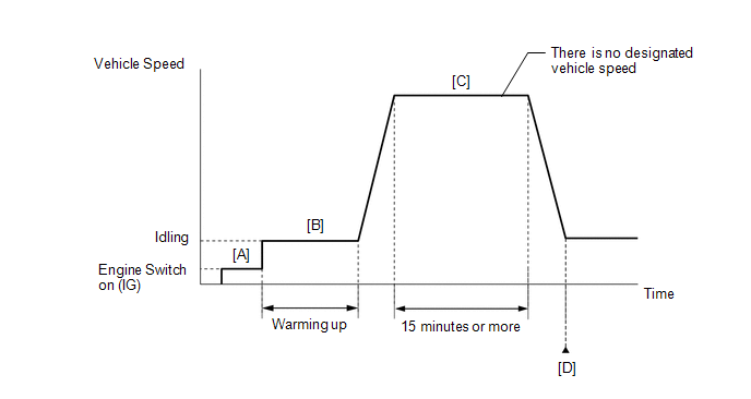
CONFIRMATION DRIVING PATTERN
- Connect the Techstream to the DLC3.
- Turn the engine switch on (IG).
- Turn the Techstream on.
- Clear the DTCs (even if no DTCs are stored, perform the clear DTC procedure).
- Turn the engine switch off and wait for at least 30 seconds.
- Turn the engine switch on (IG) [A].
- Turn the Techstream on.
- Start the engine and warm it up until the engine coolant temperature reaches 75°C (167°F) or higher [B].
-
Drive the vehicle for 15 minutes or more [C].
CAUTION:
When performing the confirmation driving pattern, obey all speed limits and traffic laws.
- Enter the following menus: Powertrain / Engine / Trouble Codes [D].
-
Read the pending DTCs.
HINT:
- If a pending DTC is output, the system is malfunctioning.
- If a pending DTC is not output, perform the following procedure.
- Enter the following menus: Powertrain / Engine / Utility / All Readiness.
- Input the DTC: P008B00.
-
Check the DTC judgment result.
Techstream Display
Description
NORMAL
- DTC judgment completed
- System normal
ABNORMAL
- DTC judgment completed
- System abnormal
INCOMPLETE
- DTC judgment not completed
- Perform driving pattern after confirming DTC enabling conditions
HINT:
- If the judgment result is NORMAL, the system is normal.
- If the judgment result is ABNORMAL, the system has a malfunction.
- If the judgment result is INCOMPLETE, perform steps [B] through [D] again.
CAUTION / NOTICE / HINT
HINT:
Read freeze frame data using the Techstream. The ECM records vehicle and driving condition information as freeze frame data the moment a DTC is stored. When troubleshooting, freeze frame data can help determine if the vehicle was moving or stationary, if the engine was warmed up or not, if the air fuel ratio was lean or rich, and other data from the time the malfunction occurred.
PROCEDURE
| 1. | CHECK OTHER DTCS OUTPUT (IN ADDITION TO DTC P008B00) |
(a) Connect the Techstream to the DLC3.
(b) Turn the engine switch on (IG).
(c) Turn the Techstream on.
(d) Enter the following menus: Powertrain / Engine / Trouble Codes.
(e) Read the DTCs.
Powertrain > Engine > Trouble Codes| Result | Proceed to |
|---|---|
| DTC P008B00 is output | A |
| DTC P008B00 and other DTCs are output | B |
HINT:
If any DTCs other than P008B00 are output, troubleshoot those DTCs first.
| B | .gif) | GO TO DTC CHART |
|
.gif)
| 2. | READ VALUE USING TECHSTREAM (FUEL PRESSURE (LOW) / FUEL PRESSURE 2) |
(a) Connect the Techstream to the DLC3.
(b) Start the engine.
(c) Turn the Techstream on.
(d) Enter the following menus: Powertrain / Engine / Data List / Fuel Pressure (Low) / Fuel Pressure 2.
Powertrain > Engine > Data List| Tester Display |
|---|
| Fuel Pressure (Low) / Fuel Pressure 2 |
(e) Record the Fuel Pressure (Low) / Fuel Pressure 2 value.
(f) Turn the engine switch off.
(g) Discharge the fuel pressure.
HINT:
DTCs may be stored during this inspection. Check for DTCs and clear them using the Techstream.
(1) Remove the EFI-MAIN NO. 2 fuse from the No. 1 engine room relay block and No. 1 junction block assembly.
(2) Start the engine.
(3) After the engine has stopped on its own, turn the engine switch off.
HINT:
If the engine does not stop naturally, perform direct injection by racing the engine to reduce the fuel pressure [Fuel Pressure (High)] and stop the engine.
(4) Crank the engine again and make sure that the engine does not start.
(5) Install the EFI-MAIN NO. 2 fuse.
(h) Turn the engine switch on (IG).
(i) Turn the Techstream on.
(j) Enter the following menus: Powertrain / Engine / Data List / Fuel Pressure (Low) / Fuel Pressure 2.
Powertrain > Engine > Data List| Tester Display |
|---|
| Fuel Pressure (Low) / Fuel Pressure 2 |
(k) Compare the Fuel Pressure (Low) / Fuel Pressure 2 value recorded with the engine running to the Fuel Pressure (Low) / Fuel Pressure 2 value currently shown on the Techstream.
| Result | Proceed to |
|---|---|
| Fuel Pressure (Low) / Fuel Pressure 2 value drops | A |
| Fuel Pressure (Low) / Fuel Pressure 2 value is maintained | B |
HINT:
Perform "Inspection After Repair" after replacing the fuel pressure sensor (for low pressure side).
Click here
| B | | REPLACE FUEL DELIVERY PIPE RH (FUEL PRESSURE SENSOR (FOR LOW PRESSURE SIDE)) |
|
| 3. | PERFORM ACTIVE TEST USING TECHSTREAM (CONTROL THE FUEL PUMP DUTY RATIO) |
(a) Install the fuel pressure gauge (for low pressure line of low pressure side).
Click here
(b) Connect the Techstream to the DLC3.
(c) Turn the engine switch on (IG).
(d) Turn the Techstream on.
(e) Enter the following menus: Powertrain / Engine / Active Test / Control the Fuel Pump Duty Ratio / Data List / Fuel Pressure (Low) / Fuel Pressure 2.
Powertrain > Engine > Active Test| Active Test Display |
|---|
| Control the Fuel Pump Duty Ratio |
| Data List Display |
|---|
| Fuel Pressure (Low) / Fuel Pressure 2 |
(f) Compare the values in the Data List using the Techstream and the fuel pressure gauge when the Active Test was performed.
Standard:
| Techstream Operation | Standard |
|---|---|
| Low | Data List value and fuel pressure gauge are within +/-50 kPa of each other |
| High |
HINT:
Perform "Inspection After Repair" after replacing the fuel pressure sensor (for low pressure side).
Click here
| NG | | REPLACE FUEL DELIVERY PIPE RH (FUEL PRESSURE SENSOR (FOR LOW PRESSURE SIDE)) |
|
| 4. | PERFORM ACTIVE TEST USING TECHSTREAM (CONTROL THE FUEL PUMP DUTY RATIO) |
(a) Install the fuel pressure gauge (for low pressure line of low pressure side).
Click here
(b) Connect the Techstream to the DLC3.
(c) Turn the engine switch on (IG).
(d) Turn the Techstream on.
(e) Enter the following menus: Powertrain / Engine / Active Test / Control the Fuel Pump Duty Ratio / Data List / Fuel Pressure (Low) / Fuel Pressure 2.
Powertrain > Engine > Active Test| Active Test Display |
|---|
| Control the Fuel Pump Duty Ratio |
| Data List Display |
|---|
| Fuel Pressure (Low) / Fuel Pressure 2 |
(f) Read the values on the Data List and the fuel pressure gauge when the Active Test was performed.
| Techstream Operation | Fuel Pressure (Low) / Fuel Pressure 2 | Fuel pressure gauge | Proceed to |
|---|---|---|---|
| Low | Below 600 kPag | Below 600 kPa (6.1 kgf/cm2, 87 psi) | A |
| 600 kPag or higher | 600 kPa (6.1 kgf/cm2, 87 psi) or higher | B |
| B | | REPLACE FUEL PUMP CONTROL ECU |
|
| 5. | CLEAR DTC |
(a) Connect the Techstream to the DLC3.
(b) Turn the engine switch on (IG).
(c) Turn the Techstream on.
(d) Clear the DTC.
Powertrain > Engine > Clear DTCs(e) Turn the engine switch off and wait for at least 30 seconds.
|
| 6. | CHECK WHETHER DTC OUTPUT RECURS (DTC P008B00) |
(a) Drive the vehicle in accordance with the driving pattern described in Confirmation Driving Pattern.
(b) Enter the following menus: Powertrain / Engine / Utility / All Readiness.
Powertrain > Engine > Utility| Tester Display |
|---|
| All Readiness |
(c) Input the DTC: P008B00.
(d) Check the DTC judgment result.
| Result | Proceed to |
|---|---|
| NORMAL (DTCs are not output) | A |
| ABNORMAL (DTC P008B00 is output) | B |
| A | | CHECK FOR INTERMITTENT PROBLEMS |
| B | | REPLACE ECM |
READ NEXT:
 EVAP System Tank Vapor Line Restricted/Blocked (P00FE00)
DTC SUMMARY DTC No. Detection Item DTC Detection Condition Trouble Area MIL Memory Note P00FE00 EVAP System Tank Vapor Line Restricted/Blocked Leak detection pump creates negati
Mass or Volume Air Flow Sensor "A" Circuit Short to Battery (P010012,P010014)
DESCRIPTION The mass air flow meter sub-assembly is a sensor that measures the intake air volume using the following built-in components:
By-pass duct (allows some of the intake air to flow past a
Mass or Volume Air Flow Sensor "A" Signal Plausibility Failure (P010064)
DESCRIPTION Refer to DTC P010012. Click here DTC No. Detection Item DTC Detection Condition Trouble Area MIL Memory Note P010064 Mass or Volume Air Flow Sensor "A" Signal Plausi
SEE MORE:
On-vehicle Inspection
ON-VEHICLE INSPECTION CAUTION / NOTICE / HINT CAUTION: To prevent injury due to contact with an operating cooling fan, keep your hands and clothing away from the cooling fans when working in the engine compartment with the engine running or the power switch on (IG). PROCEDURE 1. INSPECT ENGINE COOL
Freeze Frame Data
FREEZE FRAME DATA CHECK FREEZE FRAME DATA (a) Connect the Techstream to the DLC3. (b) Turn the engine switch on (IG). (c) Turn the Techstream on. (d) Enter the following menus: Body Electrical / Navigation System / Trouble Codes. Body Electrical > Navigation System > Trouble Codes (e) Select a
