Lexus ES: Reassembly
REASSEMBLY
PROCEDURE
1. INSTALL VACUUM PUMP VANE
(a) Apply engine oil to the vacuum pump vane and vacuum pump vane caps and install the vacuum pump vane caps to the vacuum pump vane.
(b) Apply engine oil to the vacuum pump vane with vacuum pump vane caps and install it to the vacuum pump housing.
NOTICE:
When reusing the vacuum pump vane and 2 vacuum pump vane caps, install them in the same position and orientation as when they were removed.
2. INSTALL END COVER
| (a) Install a new No. 1 O-ring to the vacuum pump housing. NOTICE:
|
|
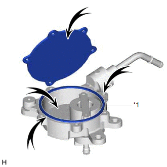
(b) Using a T30 "TORX" socket wrench, install the end cover with 5 new screws.
Torque:
7.5 N·m {76 kgf·cm, 66 in·lbf}
NOTICE:
- Hold the pump so that the pump installation surface, fitting parts and oil pump will not be damaged.
- As the housing deforms when force is applied, do not secure the housing with a tool such as a vise.
- Securely fit the T30 "TORX" socket wrench to the screws.
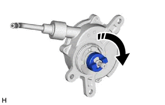
| (c) Turn the coupling clockwise as shown in the illustration and check that the coupling is not stuck or that there is no abnormal resistance. |
|
READ NEXT:
 Removal
REMOVAL PROCEDURE 1. REMOVE THROTTLE BODY WITH MOTOR ASSEMBLY Click here 2. REMOVE NO. 2 SURGE TANK STAY Click here 3. SEPARATE ENGINE WIRE (a) Remove the 2 bolts and separate the engine wire.
Components
COMPONENTS ILLUSTRATION *1 ENGINE WIRE *2 NO. 2 SURGE TANK STAY *3 EARTH WIRE - - Tightening torque for "Major areas involving basic vehicle performance such as moving/turni
SEE MORE:
Reassembly
REASSEMBLY CAUTION / NOTICE / HINT HINT:
Use the same procedure for the RH side and LH side.
The following procedure is for the LH side.
PROCEDURE 1. INSTALL REAR LIGHT PROTECTOR (a) Install a new rear light protector. 2. INSTALL REAR LIGHT GASKET (a) Install a new rear lig
Utility
UTILITY DESCRIPTION (a) Refer to the table below and then perform the necessary operation according to the part to be replaced in order to perform calibration. Parts to be Replaced / Operation Necessary Operation Skid control ECU (brake actuator assembly) Perform acceleration sensor zero
