Lexus ES: Pcv Valve
Components
COMPONENTS
ILLUSTRATION
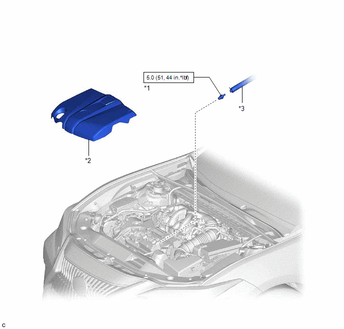
| *1 | PCV VALVE (VENTILATION VALVE SUB-ASSEMBLY) | *2 | V-BANK COVER SUB-ASSEMBLY |
| *3 | VENTILATION HOSE | - | - |
.png) | N*m (kgf*cm, ft.*lbf): Specified torque | - | - |
Removal
REMOVAL
PROCEDURE
1. REMOVE V-BANK COVER SUB-ASSEMBLY
Click here .gif)
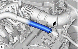
2. DISCONNECT VENTILATION HOSE
| (a) Slide the clip and disconnect the ventilation hose from the PCV valve (ventilation valve sub-assembly). |
|
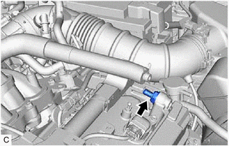
3. REMOVE PCV VALVE (VENTILATION VALVE SUB-ASSEMBLY)
| (a) Using a 22 mm deep socket wrench, remove the PCV valve (ventilation valve sub-assembly) from the cylinder head cover sub-assembly LH. |
|
Inspection
INSPECTION
PROCEDURE
1. INSPECT PCV VALVE (VENTILATION VALVE SUB-ASSEMBLY)
(a) Install a hose to the PCV valve (ventilation valve sub-assembly).
(b) Check PCV valve (ventilation valve sub-assembly) operation.
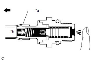
(1) Blow air into the cylinder head cover sub-assembly LH side, and check that air passes through easily.
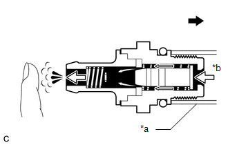
| *a | Hose |
| *b | Air |
.png) | Cylinder Head Cover Sub-assembly LH Side |
CAUTION:
Do not suck air through the valve.
Petroleum substances inside the valve are hazardous to your health.
If the result is not as specified, replace the PCV valve (ventilation valve sub-assembly).
(2) Blow air into the intake air surge tank assembly side, and check that air passes through with difficulty.
| *a | Hose |
| *b | Air |
| | Intake Air Surge Tank Assembly Side |
CAUTION:
Do not suck air through the valve.
Petroleum substances inside the valve are hazardous to your health.
If the result is not as specified, replace the PCV valve (ventilation valve sub-assembly).
(c) Remove the hose from the PCV valve (ventilation valve sub-assembly).
Installation
INSTALLATION
PROCEDURE
1. INSTALL PCV VALVE (VENTILATION VALVE SUB-ASSEMBLY)
(a) Apply a light coat of engine oil to the O-ring.
(b) Using a 22 mm deep socket wrench, install the PCV valve (ventilation valve sub-assembly) to the cylinder head cover sub-assembly LH.
Torque:
5.0 N·m {51 kgf·cm, 44 in·lbf}
NOTICE:
When reusing the PCV valve (ventilation valve sub-assembly), inspect the O-ring.
2. CONNECT VENTILATION HOSE
(a) Connect the ventilation hose to the PCV valve (ventilation valve sub-assembly) and slide the clip to secure it.
3. INSTALL V-BANK COVER SUB-ASSEMBLY
Click here .gif)
READ NEXT:
 Purge Valve
ComponentsCOMPONENTS ILLUSTRATION *1 PURGE VALVE (PURGE VSV) *2 V-BANK COVER SUB-ASSEMBLY *3 FUEL VAPOR FEED HOSE *4 NO. 1 FUEL VAPOR FEED HOSE N*m (kgf*cm, ft.*lbf): Speci
SEE MORE:
Terminals Of Ecu
TERMINALS OF ECU NOTICE:
Turning the power switch on (IG) with connectors disconnected may cause DTCs to be stored. Make sure to clear the DTCs after inspection has been performed.
Do not apply excessive force to the millimeter wave radar sensor assembly connector.
CHECK MILLIMETER WAVE RAD
Problem Symptoms Table
PROBLEM SYMPTOMS TABLE NOTICE: Before replacing the main body ECU (multiplex network body ECU), refer to Registration. Click here HINT:
Use the table below to help determine the cause of problem symptoms. If multiple suspected areas are listed, the potential causes of the symptoms are listed i
