Lexus ES: Installation
INSTALLATION
PROCEDURE
1. INSTALL REAR DIFFERENTIAL SUPPORT
(a) Install the rear differential support to the rear differential carrier assembly with 4 new bolts.
Torque:
72 N·m {734 kgf·cm, 53 ft·lbf}
2. INSTALL REAR NO. 1 DIFFERENTIAL SUPPORT
(a) Install the rear No. 1 differential support to the rear differential carrier assembly with 2 new bolts.
Torque:
55 N·m {561 kgf·cm, 41 ft·lbf}
(b) Install the rear upper differential mount stopper to the rear No. 1 differential support.
3. INSTALL REAR NO. 2 DIFFERENTIAL SUPPORT
(a) Install the rear No. 2 differential support to the rear differential carrier assembly with 2 new bolts.
Torque:
55 N·m {561 kgf·cm, 41 ft·lbf}
(b) Install the rear upper differential mount stopper to the rear No. 2 differential support.
4. INSTALL REAR DIFFERENTIAL CARRIER ASSEMBLY
NOTICE:
- Do not damage the contact surface when installing the rear differential carrier assembly.
- The remaining oil may leak out when installing the rear differential carrier assembly.
- Securely support the rear differential carrier assembly while performing this step to avoid excessively tilting or dropping the rear differential carrier assembly.
- Install the bolts and nuts with the rear differential carrier assembly secured.
(a) Support the rear differential carrier assembly with a transmission jack or equivalent.
(b) Temporarily install the rear differential carrier assembly to the rear suspension member sub-assembly with the 2 rear lower differential mount stoppers and 3 new bolts.
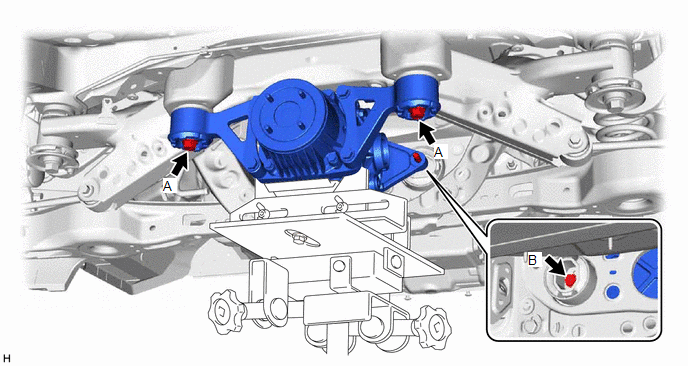
(c) Tighten the 2 bolts (A).
Torque:
86 N·m {877 kgf·cm, 63 ft·lbf}
NOTICE:
Do not tighten the bolts with the inner cylinder or rear differential mount cushion tilted.
(d) Tighten the bolt (B).
Torque:
130 N·m {1326 kgf·cm, 96 ft·lbf}
NOTICE:
Do not tighten the bolts with the inner cylinder or rear differential mount cushion tilted.
(e) Install the breather tube.
(f) Install the wire harness clamp bracket with the bolt.
Torque:
19.6 N·m {200 kgf·cm, 14 ft·lbf}
(g) Connect the 2 connectors.
(h) Engage the 2 wire harness clamps.
5. INSTALL REAR DRIVE SHAFT ASSEMBLY LH
Click here .gif)
6. INSTALL REAR DRIVE SHAFT ASSEMBLY RH
HINT:
Use the same procedure described for the LH side.
7. INSTALL REAR STABILIZER BAR
Click here
8. INSTALL PROPELLER WITH CENTER BEARING SHAFT ASSEMBLY
Click here
9. ADD DIFFERENTIAL OIL
Click here
10. INSPECT FOR DIFFERENTIAL OIL LEAK
READ NEXT:
 Reassembly
REASSEMBLY CAUTION / NOTICE / HINT NOTICE: Steps 10 to 17 are temporary reassembly procedures for adjustment purposes. PROCEDURE 1. INSTALL STRAIGHT PIN (a) Using a plastic-faced hammer, install the 4
Removal
REMOVAL CAUTION / NOTICE / HINT The necessary procedures (adjustment, calibration, initialization, or registration) that must be performed after parts are removed and installed, or replaced during rea
SEE MORE:
Headlight ECU LH Communication Stop Mode
DESCRIPTION Detection Item Symptom Trouble Area Headlight ECU LH Communication Stop Mode Any of the following conditions are met:
Communication stop for "HL AutoLeveling/AFS/AHS" is indicated on the "Communication Bus Check" screen of the Techstream.
Click here
Communication st
Diagnostic Trouble Code Chart
DIAGNOSTIC TROUBLE CODE CHART Tire Pressure Warning ECU and Receiver DTC No. Detection Item Note Link B1247 Tire Pressure Monitor Receiver Communication Stop This DTC is for main body ECU (multiplex network body ECU) C2111 Transmitter ID1 Operation Stop - C2112
