Lexus ES: Purge Valve
Components
COMPONENTS
ILLUSTRATION
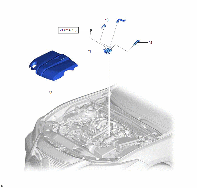
| *1 | PURGE VALVE (PURGE VSV) | *2 | V-BANK COVER SUB-ASSEMBLY |
| *3 | FUEL VAPOR FEED HOSE | *4 | NO. 1 FUEL VAPOR FEED HOSE |
.png) | N*m (kgf*cm, ft.*lbf): Specified torque | - | - |
Removal
REMOVAL
PROCEDURE
1. REMOVE V-BANK COVER SUB-ASSEMBLY
Click here .gif)
2. REMOVE PURGE VALVE (PURGE VSV)
| (a) Disconnect the purge valve (purge VSV) connector. |
|
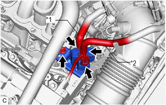
(b) Slide the clip and disconnect the fuel vapor feed hose from the purge valve (purge VSV).
(c) Disconnect the No. 1 fuel vapor feed hose from the purge valve (purge VSV).
(d) Remove the bolt and purge valve (purge VSV) from the intake air surge tank assembly.
Inspection
INSPECTION
PROCEDURE
1. INSPECT PURGE VALVE (PURGE VSV)
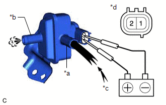
(a) Measure the resistance according to the value(s) in the table below.
Standard Resistance:
| Tester Connection | Condition | Specified Condition |
|---|---|---|
| 1 - 2 | 20°C (68°F) | 23 to 26 Ω |
If the result is not as specified, replace the purge valve (purge VSV).
| (b) Apply battery voltage between the terminals of the purge valve (purge VSV) and check that the following occurs when blowing air into the port (E). OK:
If the result is not as specified, replace the purge valve (purge VSV). |
|
Installation
INSTALLATION
PROCEDURE
1. INSTALL PURGE VALVE (PURGE VSV)
| (a) Install the purge valve (purge VSV) to the intake air surge tank assembly with the bolt. Torque: 21 N·m {214 kgf·cm, 15 ft·lbf} |
|
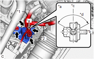
(b) Connect the No. 1 fuel vapor feed hose to the purge valve (purge VSV).
(c) Connect the fuel vapor feed hose to the purge valve (purge VSV) and slide the clip to secure it.
HINT:
Engage the clip within the area shown in the illustration.
(d) Connect the purge valve (purge VSV) connector.
2. INSTALL V-BANK COVER SUB-ASSEMBLY
Click here .gif)
READ NEXT:
 Components
COMPONENTS ILLUSTRATION *A for TMK Made *B for TMMK Made *1 ACCELERATOR PEDAL ASSEMBLY *2 ACCELERATOR PEDAL PAD *3 ACCELERATOR PEDAL SENSOR ASSEMBLY *4 NO. 1 INSTRUMENT P
SEE MORE:
Inside rear view mirror
The rear view mirror's position can
be adjusted to enable sufficient
confirmation of the rear view.
Adjusting the height of rear view
mirror
The height of the rear view mirror can
be adjusted to suit your driving posture.
Adjust the height of the rear view mirror
by moving it up and down.
Inspection
INSPECTION PROCEDURE 1. INSPECT NO. 1 VALVE ROCKER ARM SUB-ASSEMBLY (a) Turn the roller by hand to check that it turns smoothly. HINT: If the roller does not turn smoothly, replace the No. 1 valve rocker arm sub-assembly. 2. INSPECT VALVE LASH ADJUSTER ASSEMBLY NOTICE:
Keep the val
