Lexus ES: Installation
INSTALLATION
PROCEDURE
1. INSTALL NO. 2 FUEL TANK CUSHION
(a) Install a new No. 2 fuel tank cushion to the fuel tank assembly.
2. INSTALL NO. 3 FUEL TANK CUSHION
(a) Install 2 new No. 3 fuel tank cushions to the fuel tank assembly.
3. INSTALL NO. 1 FUEL TANK CUSHION
(a) Install a new No. 1 fuel tank cushion to the fuel tank assembly.
4. INSTALL NO. 4 FUEL TANK CUSHION
(a) Install 2 new No. 4 fuel tank cushions to the fuel tank assembly.
5. INSTALL FUEL RETURN VENT TUBE SUB-ASSEMBLY
(a) Install the fuel return vent tube sub-assembly to the fuel tank assembly.
6. INSTALL FUEL TANK MAIN TUBE SUB-ASSEMBLY
(a) Engage the clamp to install the fuel tank main tube sub-assembly to the fuel tank assembly.
7. INSTALL FUEL TANK ASSEMBLY
CAUTION:
The fuel tank assembly is very heavy. Be sure to follow the procedure described in the repair manual, or the fuel tank assembly may fall off the engine lifter.
.png)
(a) Set the fuel tank assembly on an engine lifter.
NOTICE:
Using height adjustment attachments and plate lift attachments, keep the fuel tank assembly horizontal.
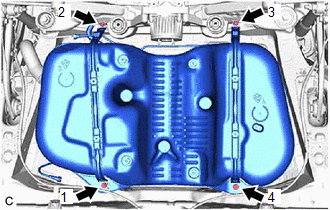
| (b) Using the engine lifter, slowly raise the fuel tank assembly, and then install the fuel tank assembly, No. 1 fuel tank band sub-assembly LH and No. 1 fuel tank band sub-assembly RH with the 4 bolts in the order shown in the illustration. Torque: 45 N·m {459 kgf·cm, 33 ft·lbf} NOTICE:
|
|
(c) Engage the clamp to connect the fuel cut off valve with tube assembly to the fuel tank vent hose sub-assembly.
Click here .gif)
(d) Connect the No. 1 fuel tank breather tube sub-assembly to the fuel pipe.
Click here
8. CONNECT INLET FUEL TANK PIPE SUB-ASSEMBLY
(a) Connect the inlet fuel tank pipe sub-assembly to the fuel tank assembly.
Click here
9. CONNECT FUEL TANK MAIN TUBE SUB-ASSEMBLY
(a) Connect the fuel tank main tube sub-assembly to the fuel pipe.
Click here
10. INSTALL NO. 1 FUEL TANK PROTECTOR SUB-ASSEMBLY
(a) Install the No. 1 fuel tank protector sub-assembly to the fuel tank assembly with the 4 clips.
11. INSTALL NO. 2 FUEL TANK PROTECTOR
(a) Install the No. 2 fuel tank protector to the No. 1 fuel tank band sub-assembly RH with the nut.
Torque:
10.5 N·m {107 kgf·cm, 8 ft·lbf}
12. INSTALL NO. 1 FLOOR UNDER COVER
Click here
13. INSTALL NO. 2 FLOOR UNDER COVER
Click here
14. INSTALL PROPELLER WITH CENTER BEARING SHAFT ASSEMBLY
Click here
15. INSTALL FUEL TANK VENT TUBE ASSEMBLY
Click here
16. INSTALL FUEL SUCTION TUBE WITH PUMP AND GAUGE ASSEMBLY
Click here
17. ADD FUEL
READ NEXT:
 Air Cleaner Filter Element
ComponentsCOMPONENTS ILLUSTRATION *1 AIR CLEANER CAP SUB-ASSEMBLY *2 AIR CLEANER FILTER ELEMENT SUB-ASSEMBLY RemovalREMOVAL PROCEDURE 1. SEPARATE AIR CLEANER CAP SUB-ASSEMBLY Click here
SEE MORE:
Parking Light/Daytime Running Light Circuit
DESCRIPTION Parking light function:
When the main body ECU (multiplex network body ECU) receives the light control switch position signal, it sends an illumination request signal to the headlight ECU sub-assembly and illuminates the parking lights.
Daytime running light function:
When the o
Throttle Actuator "A" Control System Actuator Stuck Open (P211172,P211173)
DESCRIPTION The throttle actuator is operated by the ECM and opens and closes the throttle valve using gears. The opening angle of the throttle valve is detected by the throttle position sensor, which is built into the throttle body with motor assembly. The throttle position sensor provides feedback
