Lexus ES: Parts Location
PARTS LOCATION
ILLUSTRATION
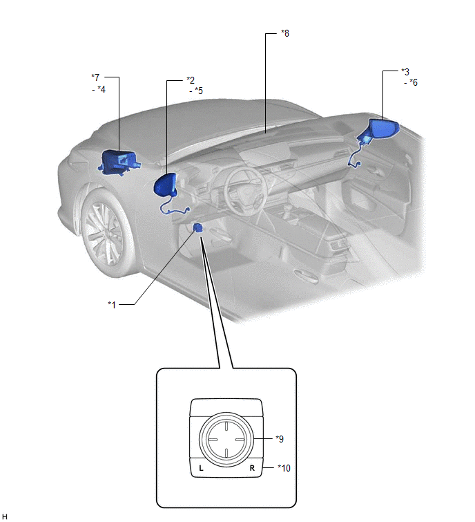
| *1 | OUTER MIRROR SWITCH ASSEMBLY | *2 | OUTER REAR VIEW MIRROR ASSEMBLY LH |
| *3 | OUTER REAR VIEW MIRROR ASSEMBLY RH | *4 | DEF RELAY |
| *5 | OUTER MIRROR LH | *6 | OUTER MIRROR RH |
| *7 | NO. 1 ENGINE ROOM RELAY BLOCK AND NO. 1 JUNCTION BLOCK ASSEMBLY - DEF FUSE - MIR HTR FUSE | *8 | INNER REAR VIEW MIRROR ASSEMBLY |
| *9 | MIRROR ADJUST SWITCH | *10 | MIRROR SELECT SWITCH |
ILLUSTRATION
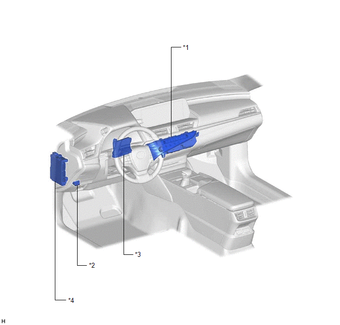
| *1 | REAR WINDOW DEFOGGER SWITCH (AIR CONDITIONING CONTROL ASSEMBLY) | *2 | DLC3 |
| *3 | AIR CONDITIONING AMPLIFIER ASSEMBLY | *4 | INSTRUMENT PANEL JUNCTION BLOCK ASSEMBLY - ECU-ACC FUSE - ECU-IG1 NO. 3 FUSE |
READ NEXT:
 System Diagram
SYSTEM DIAGRAM ELECTRICAL REMOTE CONTROL MIRROR FUNCTION MIRROR HEATER FUNCTION AUTOMATIC GLARE-RESISTANT EC MIRROR FUNCTION Communication Table Sender Receiver Signal Communication Metho
System Description
SYSTEM DESCRIPTION POWER MIRROR CONTROL SYSTEM (w/o Memory) DESCRIPTION (a) This system has the following functions: electrical remote control mirror function, power retract mirror function, mirror he
How To Proceed With Troubleshooting
CAUTION / NOTICE / HINT HINT:
Use the following procedure to troubleshoot the power mirror control system (w/o Memory).
*: Use the Techstream.
PROCEDURE 1. VEHICLE BROUGHT TO WORKSHOP
SEE MORE:
ABS Pump Motor Control Internal Electronic Failure (C052C49)
DESCRIPTION The ABS motor relay and pump motor are built into the brake actuator assembly. If the skid control ECU (brake actuator assembly) detects a malfunction in the drive circuit of the pump motor, this DTC is stored. DTC No. Detection Item DTC Detection Condition Trouble Area C052
Internal Control Module Accelerator Pedal Position Performance Internal Electronic Failure (P060D49)
MONITOR DESCRIPTION The ECM monitors the input signals of the No. 1 accelerator pedal position sensor. If the input signals and control signals deviate, this DTC is stored. DTC No. Detection Item DTC Detection Condition Trouble Area MIL Memory Note P060D49 Internal Control Modul
© 2016-2026 Copyright www.lexguide.net
