Lexus ES: Installation
INSTALLATION
CAUTION / NOTICE / HINT
HINT:
- Use the same procedure for the RH side and LH side.
- The following procedure is for the LH side.
PROCEDURE
1. INSTALL REAR COMBINATION LIGHT ASSEMBLY (for TMMK Made)
2. INSTALL REAR BUMPER UPPER RETAINER (for TMMK Made)
Click here .gif)
3. INSTALL REAR BUMPER ASSEMBLY (for TMMK Made)
for Single Type:
Click here
for Dual Type:
Click here
4. INSTALL REAR COMBINATION LIGHT LENS AND BODY (for TMC Made)
(a) Engage the grommet.
(b) Engage the 3 guides and pin to temporarily install the rear combination light lens and body as shown in the illustration.
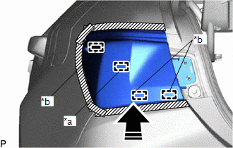
| *a | Pin |
| *b | Guide |
.png) | Install in this Direction |
(c) Install the rear combination light lens and body with the 2 screws.
(d) Remove the protective tape.
(e) Connect the connector.
5. INSTALL REAR COMBINATION LIGHT COVER
(a) Engage the guide and 2 claws as shown in the illustration.
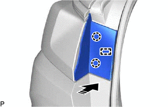
| | Install in this Direction |
(b) Engage the 2 claws to install the rear combination light cover as shown in the illustration.
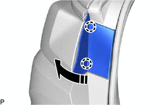
| | Install in this Direction |
6. INSTALL LUGGAGE COMPARTMENT TRIM INNER COVER LH (for LH Side)
Click here
7. INSTALL LUGGAGE COMPARTMENT TRIM INNER COVER RH (for RH Side)
Click here
8. INSTALL LUGGAGE COMPARTMENT TRIM COVER LH (for LH Side)
Click here
9. INSTALL LUGGAGE COMPARTMENT TRIM COVER RH (for RH Side)
Click here
10. INSTALL REAR FLOOR FINISH PLATE
Click here
11. INSTALL SPARE WHEEL COVER TRAY
Click here
12. INSTALL LUGGAGE COMPARTMENT FLOOR MAT
Click here
READ NEXT:
 Components
COMPONENTS ILLUSTRATION *A w/ Power Trunk Lid System - - *1 LUGGAGE COMPARTMENT DOOR COVER *2 LUGGAGE LOCK CONTROL CABLE PLATE *3 SWITCH BEZEL - - ILLUSTRATION *1
Removal
REMOVAL CAUTION / NOTICE / HINT HINT:
Use the same procedure for the RH side and LH side.
The following procedure is for the LH side.
PROCEDURE 1. REMOVE LUGGAGE LOCK CONTROL CABLE PLATE Click
SEE MORE:
Utility
UTILITY FREEZE FRAME DATA NOTICE:
Freeze frame data is stored and updated each time the brakes are operated. Only the latest 30 sets of data are stored.
Using the Techstream, make sure to save the data before performing a reproduction test as the data will be updated. HINT: The freeze frame dat
Side Camera LH Response Malfunction (C2A6B)
DESCRIPTION During self diagnosis of the parking assist ECU, the parking assist ECU sends display mode ID signals to the side television camera assembly LH. This DTC is stored when the output of the side television camera assembly LH does not match the expected output. DTC No. Detection Item
