Lexus ES: Start Up Signal Circuit between Radio Receiver Assembly and Navigation ECU
Lexus ES (XZ10) Service Manual / Audio & Visual & Telematics / Navigation / Multi Info Display / Navigation System (for Gasoline Model) / Start Up Signal Circuit between Radio Receiver Assembly and Navigation ECU
DESCRIPTION
This circuit includes the navigation ECU and radio receiver assembly.
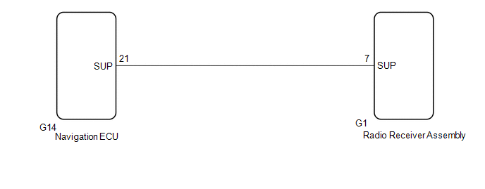
WIRING DIAGRAM
PROCEDURE
| 1. | CHECK HARNESS AND CONNECTOR (RADIO RECEIVER ASSEMBLY - NAVIGATION ECU) |
(a) Disconnect the G1 radio receiver assembly connector.
(b) Disconnect the G14 navigation ECU connector.
(c) Measure the resistance according to the value(s) in the table below.
Standard Resistance:
| Tester Connection | Condition | Specified Condition |
|---|---|---|
| G1-7 (SUP) - G14-21 (SUP) | Always | Below 1 Ω |
| G1-7 (SUP) or G14-21 (SUP) - Body ground | Always | 10 kΩ or higher |
| OK |  | PROCEED TO NEXT SUSPECTED AREA SHOWN IN PROBLEM SYMPTOMS TABLE |
.gif)
| NG | | REPAIR OR REPLACE HARNESS OR CONNECTOR |
READ NEXT:
 Steering Pad Switch Circuit
DESCRIPTION This circuit sends an operation signal from the steering pad switch assembly to the radio receiver assembly. If there is an open in the circuit, the navigation system cannot be operated us
Stereo Jack Adapter Light does not Illuminate
DESCRIPTION Power is supplied to the No. 1 stereo jack adapter assembly illumination from the radio receiver assembly. WIRING DIAGRAM CAUTION / NOTICE / HINT NOTICE:
Depending on the parts that ar
Switch Lights of Remote Touch Always Illuminate or cannot be Controlled Using Rheostat
DESCRIPTION Power is supplied to the remote touch (remote operation controller assembly) illumination when the light control switch is in the tail or head position. HINT:
When the remote touch (rem
SEE MORE:
Components
COMPONENTS ILLUSTRATION *A for A25A-FKS, A25A-FXS *B for 2GR-FKS *1 FRONT WHEEL OPENING EXTENSION PAD LH *2 FRONT WHEEL OPENING EXTENSION PAD RH *3 NO. 1 ENGINE UNDER COVER *4 NO. 2 ENGINE UNDER COVER *5 NO. 2 ENGINE UNDER COVER ASSEMBLY *6 NO. 3 ENGINE UNDER
Position Initialization Incomplete (B2343)
DESCRIPTION This DTC is stored when the sliding roof ECU (sliding roof drive gear assembly) has not been initialized. DTC No. Detection Item DTC Detection Condition Trouble Area B2343 Position Initialization Incomplete Sliding roof ECU (sliding roof drive gear assembly) has not been
© 2016-2026 Copyright www.lexguide.net
