Lexus ES: Low or High Power Supply Voltage (C1241)
DESCRIPTION
If a malfunction in the power source circuit occurs, or a malfunction in communication with the skid control ECU (brake actuator assembly) or in a speed sensor occurs, the 4WD ECU assembly will prohibit operations by the fail-safe function.
| DTC No. | Detection Item | DTC Detection Condition | Trouble Area |
|---|---|---|---|
| C1241 | Low or High Power Supply Voltage |
|
|
| Vehicle Condition | |||||
|---|---|---|---|---|---|
| Pattern 1 | Pattern 2 | Pattern 3 | Pattern 4 | ||
| Diagnosis Condition | At a vehicle speed of 3 km/h (2 mph) or more | ○ | - | - | - |
| With the IG1 terminal voltage 9.5 V or less | - | ○ | - | - | |
| With the IG1 terminal voltage 17 V or more | - | - | - | ○ | |
| Malfunction Status | Voltage of IG1 terminal is 9.5 V or less. | ○ | - | - | - |
| Communication with the skid control ECU (brake actuator assembly) is impossible. | - | ○ | - | ○ | |
| Vehicle speed sensor voltage is reduced. | - | - | ○ | - | |
| Detection Time | 10 seconds or more | - | 60 seconds or more | 3 seconds or more | |
| Number of Trips | 1 trip | 1 trip | 1 trip | 1 trip | |
HINT:
DTC will be output when conditions for any of the patterns in the table above are met.
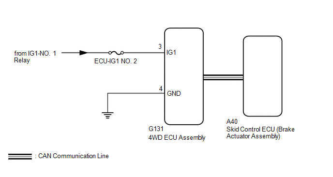
WIRING DIAGRAM
CAUTION / NOTICE / HINT
NOTICE:
Inspect the fuses for circuits related to this system before performing the following inspection procedure.
PROCEDURE
| 1. | CHECK FOR DTC (CAN COMMUNICATION SYSTEM AND ELECTRONICALLY CONTROLLED BRAKE SYSTEM) |
(a) Check if CAN communication system DTCs are output.
Click here .gif)
(b) Start the engine.
(c) Drive the vehicle, accelerate to a speed of 3 km/h (2 mph) or more for 60 seconds or more, and check if the speed sensor DTC (electronically controlled brake system DTC) is output.
Chassis > Brake/EPB > Trouble Codes| Result | Proceed to |
|---|---|
| Neither CAN communication system DTC nor speed sensor DTC (electronically controlled brake system DTC) is output | A |
| CAN communication system DTC is output | B |
| Speed sensor DTC (electronically controlled brake system DTC) is output | C |
| B | .gif) | GO TO CAN COMMUNICATION SYSTEM (HOW TO PROCEED WITH TROUBLESHOOTING) |
| C | | REPAIR CIRCUIT INDICATED BY OUTPUT CODE (ELECTRONICALLY CONTROLLED BRAKE SYSTEM) |
|
.gif)
| 2. | INSPECT BATTERY |
(a) Check the battery voltage.
Standard Voltage:
11 to 14 V
| NG | | CHECK CHARGING SYSTEM |
|
| 3. | CHECK HARNESS AND CONNECTOR (IG1 TERMINAL) |
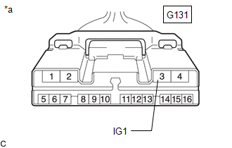
| (a) Disconnect the G131 4WD ECU assembly connector. |
|
(b) Turn the engine switch on (IG).
(c) Measure the voltage according to the value(s) in the table below.
Standard Voltage:
| Tester Connection | Condition | Specified Condition |
|---|---|---|
| G131-3 (IG1) - Body ground | Engine switch on (IG) | 11 to 14 V |
| NG | | REPAIR OR REPLACE HARNESS OR CONNECTOR |
|
| 4. | CHECK HARNESS AND CONNECTOR (GND TERMINAL) |
(a) Turn the engine switch off.
(b) Measure the resistance according to the value(s) in the table below.
Standard Resistance:
| Tester Connection | Condition | Specified Condition |
|---|---|---|
| G131-4 (GND) - Body ground | Always | Below 1 Ω |
| NG | | REPAIR OR REPLACE HARNESS OR CONNECTOR |
|
| 5. | RECONFIRM DTC |
(a) Clear the DTC.
Chassis > Four Wheel Drive > Clear DTCs(b) Start the engine.
(c) Drive the vehicle, accelerate to a speed of 3 km/h (2 mph) or more, and check if the same DTC is output.
Chassis > Four Wheel Drive > Trouble Codes| Result | Proceed to |
|---|---|
| DTC is output | A |
| DTC is not output | B |
HINT:
Reinstall the sensor, connectors, etc. and restore the vehicle to its prior condition before rechecking DTCs.
| A | | REPLACE 4WD ECU ASSEMBLY |
| B | | CHECK FOR INTERMITTENT PROBLEMS |
READ NEXT:
 Engine Circuit Malfunction (C1280)
DESCRIPTION If a malfunction in the ECM circuit occurs, the 4WD ECU assembly will output this DTC. DTC No. Detection Item DTC Detection Condition Trouble Area C1280 Engine Circuit Malfu
ABS Malfunction (C1296)
DESCRIPTION If a malfunction in the speed sensor signal circuit or yaw rate and acceleration sensor (airbag ECU assembly) circuit occurs, the 4WD ECU assembly will output this DTC. The airbag ECU asse
Steering Angle Sensor (C1297)
DESCRIPTION The 4WD ECU assembly determines that the vehicle is turning based on the signals sent from the steering sensor. The steering sensor signal is sent to the 4WD ECU assembly via CAN communica
SEE MORE:
FL Speed Sensor Wrong Installation (X0451)
DESCRIPTION Code Tester Display Measurement Item Trouble Area X0451 FL Speed Sensor Wrong Installation History of front speed sensor LH being installed incorrectly Front speed sensor LH PROCEDURE 1. CHECK FOR DTCs (HEALTH CHECK) (a) Perform the Health Check using the T
Removal
REMOVAL CAUTION / NOTICE / HINT The necessary procedures (adjustment, calibration, initialization, or registration) that must be performed after parts are removed and installed, or replaced during steering knuckle removal/installation are shown below. Necessary Procedures After Parts Removed/Install
