Lexus ES: Installation
Lexus ES (XZ10) Service Manual / Drivetrain / Gf1a (transfer / 4wd / Awd) / Transfer Assembly / Installation
INSTALLATION
PROCEDURE
1. INSTALL TRANSFER ASSEMBLY
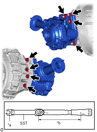
| (a) Using SST and a 17 mm union nut wrench, install the transfer assembly to the automatic transaxle assembly with the 8 nuts. SST: 09961-00950 Torque: Specified tightening torque : 68.6 N·m {700 kgf·cm, 51 ft·lbf} HINT:
|
|
2. INSTALL REAR ENGINE MOUNTING BRACKET SUB-ASSEMBLY
Click here .gif)
3. INSTALL NO. 1 PROPELLER SHAFT HEAT INSULATOR BRACKET SUB-ASSEMBLY
(a) Install the No. 1 propeller shaft heat insulator bracket sub-assembly to the transfer assembly with the 2 bolts.
Torque:
25 N·m {255 kgf·cm, 18 ft·lbf}
4. INSTALL PROPELLER SHAFT HEAT INSULATOR
Click here
5. INSTALL AUTOMATIC TRANSAXLE ASSEMBLY
Click here
READ NEXT:
 Reassembly
REASSEMBLY CAUTION / NOTICE / HINT NOTICE: Steps 9 to 16 are temporary reassembly procedures for adjustment purposes. PROCEDURE 1. INSTALL BREATHER OIL DEFLECTOR (a) Install a new breather oil deflec
Transfer Case Front Oil Seal (for Lh Side)
ComponentsCOMPONENTS ILLUSTRATION *1 TRANSFER AND TRANSAXLE SETTING STUD BOLT *2 TRANSFER CASE OIL SEAL N*m (kgf*cm, ft.*lbf): Specified torque ● Non-reusable part MP gr
SEE MORE:
Right Front Wheel Speed Sensor Circuit Intermittent (C05061F)
DESCRIPTION Refer to DTC C050612 Click here DTC No. Detection Item DTC Detection Condition Trouble Area C05061F Right Front Wheel Speed Sensor Circuit Intermittent
The speed sensor signal is excessively noisy.
The calculated change in wheel speed is more than 980 m/s2 for 5*1
System Description
SYSTEM DESCRIPTION PANORAMIC MOON ROOF SYSTEM DESCRIPTION (a) The panoramic moon roof system controls the sliding roof operation using the sliding roof ECU (sliding roof drive gear assembly) and roof sunshade ECU (sliding roof drive gear assembly). Operating the panoramic moon roof switch (map light
© 2016-2026 Copyright www.lexguide.net
