Lexus ES: Parts Location
PARTS LOCATION
ILLUSTRATION
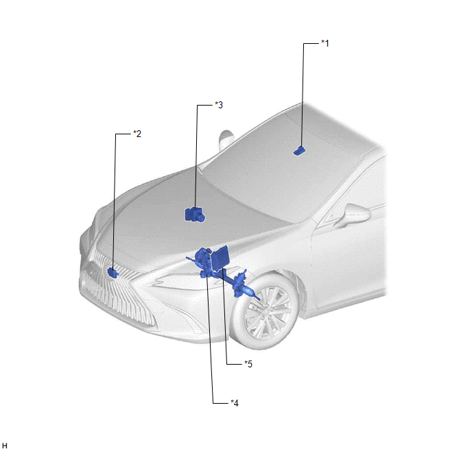
| *1 | FORWARD RECOGNITION CAMERA | *2 | MILLIMETER WAVE RADAR SENSOR ASSEMBLY |
| *3 | BRAKE ACTUATOR ASSEMBLY - SKID CONTROL ECU | *4 | RACK AND PINION POWER STEERING GEAR ASSEMBLY - POWER STEERING ECU |
| *5 | ECM | - | - |
ILLUSTRATION
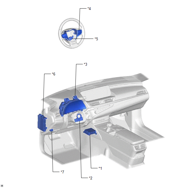
| *1 | AIRBAG ECU ASSEMBLY - YAW RATE SENSOR | *2 | STEERING SENSOR |
| *3 | COMBINATION METER ASSEMBLY - MULTI-INFORMATION DISPLAY - LTA INDICATOR - LTA BUZZER | *4 | STEERING PAD SWITCH ASSEMBLY - LTA MAIN SWITCH - FUNCTION SWITCH (CUSTOMIZE SWITCH) |
| *5 | STEERING VIBRATION ECU | *6 | INSTRUMENT PANEL JUNCTION BLOCK ASSEMBLY - ECU-IG1 NO. 3 FUSE |
| *7 | DLC3 | - | - |
READ NEXT:
 System Diagram
SYSTEM DIAGRAM
How To Proceed With Troubleshooting
CAUTION / NOTICE / HINT HINT:
Use the following procedure to troubleshoot the lane control system.
*: Use the Techstream.
PROCEDURE 1. VEHICLE BROUGHT TO WORKSHOP
NEXT
Customize Parameters
CUSTOMIZE PARAMETERS CUSTOMIZE LTA NOTICE:
When the customer requests a change in a function, first make sure that the function can be customized.
Be sure to make a note of the current settings b
SEE MORE:
Utility
UTILITY OPERATION HISTORY HINT: History of Reason for Operation: The windshield wiper motor assembly stores Operation History which can be read using the Techstream, when a malfunction of the wiper and washer system occurs. Click here (a) Connect the Techstream to the DLC3. (b) Turn the power swit
Lost Communication with Cruise Control Module Missing Message (U010487,U012287,U029387)
DESCRIPTION The hybrid vehicle control ECU communicates with each sensor and ECU via CAN communication. If any malfunction is detected in a CAN communication circuit, one or more CAN communication system DTCs are stored. DTC No. Detection Item DTC Detection Condition Trouble Area MIL DT
© 2016-2026 Copyright www.lexguide.net
