Lexus ES: Parts Location
PARTS LOCATION
ILLUSTRATION
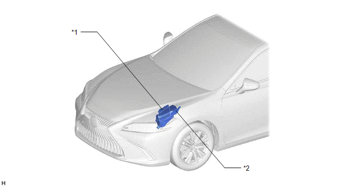
| *1 | ECM | *2 | NO. 1 ENGINE ROOM RELAY BLOCK AND NO. 1 JUNCTION BLOCK ASSEMBLY - ST RELAY - EFI-MAIN NO. 1 FUSE - J/B-B FUSE - ETCS FUSE |
ILLUSTRATION
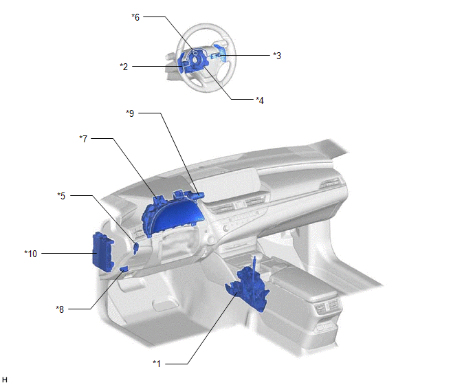
| *1 | SHIFT LOCK CONTROL UNIT ASSEMBLY - TRANSMISSION CONTROL SWITCH | *2 | SHIFT PADDLE SWITCH LH (TRANSMISSION SHIFT SWITCH ASSEMBLY) |
| *3 | SHIFT PADDLE SWITCH RH (TRANSMISSION SHIFT SWITCH ASSEMBLY) | *4 | SPIRAL CABLE SUB-ASSEMBLY |
| *5 | STOP LIGHT SWITCH ASSEMBLY | *6 | NO. 1 SWITCH WIRE |
| *7 | COMBINATION METER ASSEMBLY | *8 | DLC3 |
| *9 | DRIVE MODE SELECT SWITCH (COMBINATION SWITCH ASSEMBLY) | *10 | INSTRUMENT PANEL JUNCTION BLOCK ASSEMBLY - STOP FUSE - ECU-ACC FUSE - BKUP LP FUSE - ECU-IG1 NO. 3 FUSE |
ILLUSTRATION
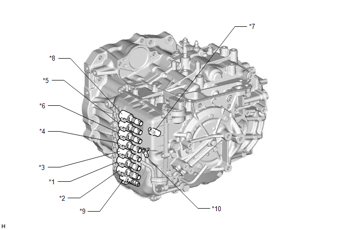
| *1 | SOLENOID (SL1) VALVE | *2 | SOLENOID (SL2) VALVE |
| *3 | SOLENOID (SL3) VALVE | *4 | SOLENOID (SL4) VALVE |
| *5 | SOLENOID (SL5) VALVE | *6 | SOLENOID (SL6) VALVE |
| *7 | SOLENOID (SL) VALVE | *8 | SOLENOID (SLU) VALVE |
| *9 | SOLENOID (SLT) VALVE | *10 | TRANSMISSION WIRE - ATF TEMPERATURE SENSOR |
ILLUSTRATION
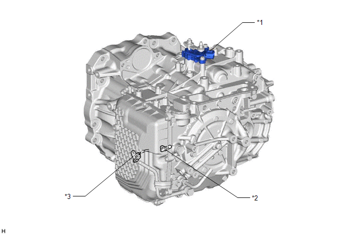
| *1 | PARK/NEUTRAL POSITION SWITCH ASSEMBLY | *2 | TRANSMISSION REVOLUTION SENSOR (NT) |
| *3 | TRANSMISSION REVOLUTION SENSOR (NC) | - | - |
READ NEXT:
 Precaution
PRECAUTION PRECAUTION FOR DISCONNECTING CABLE FROM NEGATIVE BATTERY TERMINAL NOTICE: When disconnecting the cable from the negative (-) battery terminal, initialize the following system(s) after the c
Problem Symptoms Table
PROBLEM SYMPTOMS TABLE HINT:
Use the table below to help determine the cause of problem symptoms. If multiple suspected areas are listed, the potential causes of the symptoms are listed in order of
Registration
REGISTRATION CAUTION / NOTICE / HINT NOTICE:
When the automatic transaxle assembly is replaced, the transaxle compensation code must be registered to the ECM (proceed to Procedure 1).
After the aut
SEE MORE:
Hybrid/EV Battery Energy Control Module Processor to Monitoring Processor Missing Message (P060687)
DESCRIPTION The battery ECU assembly monitors its internal operation and will store these DTCs when it detects an internal malfunction. DTC No. Detection Item DTC Detection Condition Trouble Area MIL Warning Indicate P060687 Hybrid/EV Battery Energy Control Module Processor to Mon
Removal
REMOVAL PROCEDURE 1. REMOVE LUGGAGE COMPARTMENT FLOOR MAT Click here 2. REMOVE SPARE WHEEL COVER TRAY Click here 3. REMOVE REAR FLOOR FINISH PLATE Click here 4. REMOVE LUGGAGE COMPARTMENT DOOR WEATHERSTRIP (a) Remove the luggage compartment door weatherstrip.
