Lexus ES: Precaution
PRECAUTION
PRECAUTION FOR DISCONNECTING CABLE FROM NEGATIVE BATTERY TERMINAL
NOTICE:
When disconnecting the cable from the negative (-) battery terminal, initialize the following system(s) after the cable is reconnected:
| System | See Procedure |
|---|---|
| Lane Control System (for Gasoline Model) | |
| Pre-collision System (for Gasoline Model) | |
| Parking Support Brake System (for Gasoline Model) | |
| Lighting System (for Gasoline Model) | |
| Parking Assist Monitor System (for Gasoline Model) | |
| Panoramic View Monitor System (for Gasoline Model) | |
| Power Trunk Lid System (for Gasoline Model) |
PROCEDURES NECESSARY WHEN ECU OR OTHER PARTS ARE REPLACED
NOTICE:
-
If automatic transaxle parts are replaced, perform the following as necessary referring to the table below: Parts Replacement Compensation Table
*1: When replacing with a new ECM *2: When replacing with an ECM which was installed to another vehicle
Replaced Part
Transaxle Compensation Code
Reset Memory (Learned Values)
Road Test
Automatic transaxle assembly
Input
Reset
Necessary
Transmission valve body assembly
Initialize
Reset
Necessary
Solenoid (SL1, SL2, SL3, SL4, SL5 and/or SL6) valve
Initialize
Reset
Necessary
ECM
(If possible, read the transaxle compensation code from the previous ECM)
Possible to read transaxle compensation code
Input (Into the new ECM)
-*1
Reset*2
Necessary
Impossible to read transaxle compensation code
Initialize
-*1
Reset*2
Necessary
-
Registration of the transaxle compensation code.
Click here
.gif)
-
Initialization of the transaxle compensation code.
Click here
-
Road test.
Click here
-
Reset Memory (learned values).
Click here
HINT:
Reset Memory cannot be completed by only reconnecting the cable to the negative (-) battery terminal.
-
Registration of the transaxle compensation code.
-
Perform Registration (VIN registration) when replacing the ECM.
Click here
-
Before replacing the ECM or certification ECU (smart key ECU assembly), refer to Registration.
Click here
-
If either of the following conditions is met, perform ATF Thermal Degradation Estimate Reset:
Click here
-
The ATF has been replaced.
HINT:
If 50000 or more is displayed for the Data List item "ATF Thermal Degradation Estimate", thermal degradation of the ATF is suspected. Perform ATF Thermal Degradation Estimate Reset after replacing the ATF.
- Approximately 50% or more of the ATF has been replaced during a repair of the transaxle or a similar operation.
-
The ATF has been replaced.
HANDLING PRECAUTIONS
CAUTION:
-
Do not perform a stall test if there are any people or objects near the vehicle.
.png)
- The vehicle could begin moving suddenly, resulting in a serious accident.
-
Do not perform a stall test if any wheel chocks are out of position.
.png)
- The vehicle could begin moving suddenly, resulting in a serious accident.
-
Do not perform the stall test on a slippery or low-friction surface that could allow the tires to spin.
.png)
- The vehicle could begin moving suddenly, resulting in a serious accident.
-
Do not blow compressed air without wearing safety glasses.
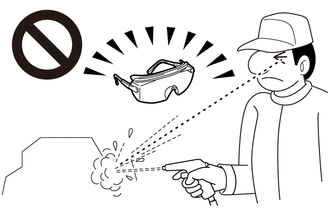
- Automatic Transaxle Fluid (ATF) could enter your eyes, possibly resulting in blindness.
NOTICE:
- The automatic transaxle assembly is composed of precision-made parts. Careful inspection before reassembly is necessary because even a small nick could cause fluid leakage or affect performance.
- The procedures are organized so that you work on only one component group at a time. This will help avoid confusion with similar-looking parts of different sub-assemblies being on your workbench at the same time.
- The component groups are inspected and repaired from the converter housing side.
- Whenever possible, complete the inspection, repair and reassembly before proceeding to the next component group. If a defect is found in a certain component group during reassembly, inspect and repair this group immediately. If a component group cannot be assembled because parts are being ordered, be sure to keep all parts of the group in a separate container while proceeding with disassembly, inspection, repair and reassembly of other component groups.
- Use of Toyota Genuine ATF WS is recommended.
- All disassembled parts should be cleaned, and compressed air should be blown through any fluid passages and holes.
- Dry all parts with compressed air. Never use a piece of cloth.
- The recommended ATF or kerosene should be used for cleaning.
- After cleaning, the parts should be arranged in the order they were removed for efficient inspection, repair and reassembly.
- New brake discs and clutch discs must be soaked in ATF for at least 15 minutes before reassembly.
- All oil seal rings, clutch discs, clutch plates, rotating parts, and sliding surfaces should be coated with ATF prior to reassembly.
- All old gaskets and rubber O-rings must be replaced.
- Do not apply adhesive cement to gaskets or similar parts.
- Make sure that the ends of snap rings are not aligned with any cutouts. Make sure that snap rings are correctly installed into the grooves.
- If a worn bushing is to be replaced, the sub-assembly containing the bushing must also be replaced.
- Check the thrust bearings and races for wear or damage. Replace them if necessary.
- Use petroleum jelly to keep parts in place.
-
When working with seal packing (FIPG), observe the following:
- Using a razor blade and a gasket scraper, remove all of the old seal packing (FIPG) from the gasket surface.
- Thoroughly clean all components to remove any seal packing (FIPG).
- Clean both sealing surfaces with a non-residue solvent.
- Parts must be reassembled within 10 minutes of application. Otherwise, the seal packing (FIPG) must be removed and reapplied.
READ NEXT:
 Problem Symptoms Table
PROBLEM SYMPTOMS TABLE HINT:
Use the table below to help determine the cause of problem symptoms. If multiple suspected areas are listed, the potential causes of the symptoms are listed in order of
Registration
REGISTRATION CAUTION / NOTICE / HINT NOTICE:
When the automatic transaxle assembly is replaced, the transaxle compensation code must be registered to the ECM (proceed to Procedure 1).
After the aut
Road Test
ROAD TEST PROBLEM SYMPTOM CONFIRMATION (a) Based on the result of the customer problem analysis, try to reproduce the symptoms. If the problem is that the transaxle does not shift up, shift down, or t
SEE MORE:
Installation
INSTALLATION PROCEDURE 1. INSTALL PORT FUEL INJECTOR ASSEMBLY HINT: Perform "Inspection After Repair" after replacing a port fuel injector assembly. Click here (a) Apply a light coat of spindle oil or gasoline to 6 new O-rings, and install one to each port fuel injector assembly. NOTICE: Check th
Heated steering wheel/seat heaters/
seat ventilators
Heated steering wheel
Warms up the grip of the steering wheel
Seat heaters
Warm up the seat upholstery
Seat ventilators
Maintain good air flow by sucking air
into the seats
Press the "MENU" button on the
Remote Touch and select "Climate"
to display the air conditioning control
s
