Lexus ES: Removal
REMOVAL
PROCEDURE
1. SECURE VEHICLE
(a) Fully apply the parking brake and chock a wheel.
CAUTION:
- Make sure to apply the parking brake and chock a wheel before performing this procedure.
- If the vehicle is not secure and the shift lever is moved to N, the vehicle may suddenly move, possibly resulting in an accident or serious injury.
.png)
2. REMOVE FRONT WHEEL OPENING EXTENSION PAD RH
Click here .gif)
3. REMOVE FRONT WHEEL OPENING EXTENSION PAD LH
Click here
4. REMOVE NO. 1 ENGINE UNDER COVER
Click here
5. REMOVE NO. 2 ENGINE UNDER COVER ASSEMBLY
Click here
6. REMOVE COOL AIR INTAKE DUCT SEAL
Click here
7. REMOVE INLET AIR CLEANER ASSEMBLY
Click here
8. REMOVE NO. 1 ENGINE COVER SUB-ASSEMBLY
Click here
9. REMOVE AIR CLEANER ASSEMBLY WITH AIR CLEANER HOSE
Click here
10. DISCONNECT TRANSMISSION CONTROL CABLE ASSEMBLY
(a) Move the shift lever to N.
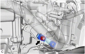
| (b) Remove the nut and disconnect the transmission control cable assembly from the control shaft lever. |
|
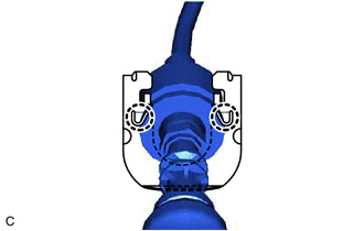
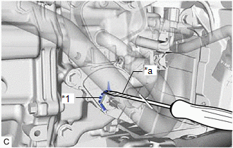
| (c) Using a screwdriver, disengage the 4 claws and disconnect the transmission control cable assembly with the clip from the No. 1 transmission control cable bracket. |
|
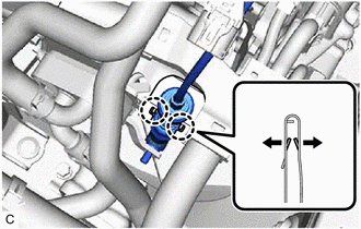
| (d) Using a screwdriver, disengage the 2 claws and remove the clip from the transmission control cable assembly. |
|
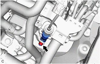
11. REMOVE SHIFT LEVER POSITION SENSOR
| (a) Disconnect the shift lever position sensor connector. |
|
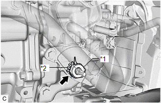
| (b) Remove the nut, washer and control shaft lever from the shift lever position sensor. |
|
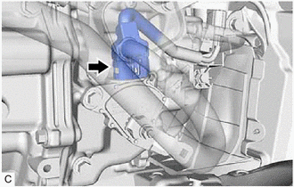
| (c) Using a screwdriver with its tip wrapped with protective tape, pry out the tabs of the lock plate. |
|
| (d) Remove the lock nut and lock plate from the shift lever position sensor. |
|
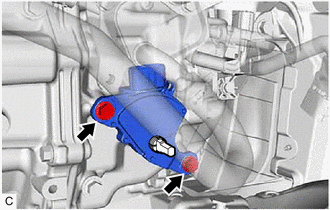
| (e) Remove the 2 bolts and shift lever position sensor from the hybrid vehicle transaxle assembly. |
|
READ NEXT:
 Components
COMPONENTS ILLUSTRATION *1 SHIFT LEVER KNOB SUB-ASSEMBLY *2 SHIFT LOCK RELEASE BUTTON COVER *3 TRANSMISSION CONTROL CABLE ASSEMBLY *4 TRANSMISSION FLOOR SHIFT ASSEMBLY *5 REA
Disassembly
DISASSEMBLY PROCEDURE 1. REMOVE SHIFT POSITION INDICATOR (a) Disengage the 2 clamps to disconnect the wire harness. (b) Remove the 2 screws. (c) Disengage the claw and
SEE MORE:
Brake
BRAKE
INSPECT BRAKE LINE PIPES AND HOSES
HINT:
Work in a well-lighted area. Turn the front wheels fully to the right or left
before beginning the inspection.
(a) Using a mirror, check the entire circumference and length of the brake lines
and hoses for:
Damage
Wear
Deformatio
Diagnosis System
DIAGNOSIS SYSTEM DESCRIPTION (a) Sliding roof system data and Diagnostic Trouble Codes (DTCs) can be read through the vehicle Data Link Connector 3 (DLC3). When the system seems to be malfunctioning, use the Techstream to check for malfunctions and perform repairs. CHECK DLC3 (a) Check the DLC3. Cli
